Don't like the adverts?  Click here to remove them

iwan's hdj81

For me the most obvious option would be to cut down the bracket where it fouls on the manual cross member and simply weld them in place. Looking at the brackets, they are the sort of thing that Ben would make up easily with his workshop equipment to make something similar just on the bench would takes some time. Hence my interest in the factory made brackets that Geert has.

If I had to make some, I'd undo the rear eye, leave the CC plates on and tip the axle till I got the UJ angles I wanted and then make the bracket to that.
 
I can't remember which brackets exactly I have. I can measure the distance that the arms are dropped. I have OME 850J springs in front and the castor is perfect! (with orginal bushings). I think those springs are 3" lift.
The costed me 250 euros a year ago.
 
Cool a measure would be great at some point.. see ive bought 125mm lift front springs and to get hold of exact drop plates to match would be lucky. I have a set of 100mm drop plates booked. Thinking there could be an element of fine tuning with castor correction bushes... all good!! Thanks
 
On the standard 80 the front axle pinion is not in the same relative plane as the front transfer output flange. The front prop shaft is run out of phase which cancels out the difference in rotational speed.

If you lift the body the front flange angles will be more out of relative plane than the rear as the front axle turns on the link radius whilst the rear has twin trailing links keeping the rear flange constant. Perhaps body lifts lead to more front axle failures especially if the centre dif is locked whereupon the front differences in rotation are not diluted by the rear.
 
125mm lift? That's a lot! But castor measurement is the only way to go. So much is depending on the extras on the truck. Much weight in front easily makes a 125mm lift 100mm or much less!
 
Don't like the adverts?  Click here to remove them
Recieved wisdom says forget bushes. They are the Devil's work. Basically they're a bodge I reckon. Go with plates at which ever end you feel is right. But bushes best left natural I feel. You only need to get somewhere close to 3 degrees of flange angle difference FAD we could call it. It would be very easy to measure rear eye drop distance per degree of rotation of the axle. Just strap your smart phone on the flange and move the arm downwards. Be really neat if 1" of drop meant 1 degree of rotation but I fear that's not going to happen If I had a scrap chassis, I'd cut the OE brackets off and extend them then weld them onto the vehicle

Ohhhh Karl.......
 
The 60 series drive flanges are the same too. Which made me think best to measure the castor on the knuckle. For exact reading. . Thanks Frank :thumbup:
 
Last edited:
Frank, that's really interesting and something that actually I had been pondering. Where did you get that gem from? I was looking in the FSM hoping to find something about setting up the props but all I could fins was them being set square as it were. I maybe mistakenly phased my prop straight yesterday and it's not right. I have a definite speed related dub dub dub now. Maybe with a lift such as mine all I need is to have the prop out of phase by the correct amount and that sorts it. I'd appreciate you views on that. It's a free fix. Maybe there is something in the FSM for the front prop that I missed. If it's not supposed to be straight it bloody well is now. Have got some match marks on there somewhere I think.
 
Luckily I have a spare 80 I can copy from, but just looked in the FSM again and the prop is show aligned dead straight. There's nothing at all about how to off set the phase. I did jack up the front ans pin the wheels and have to say that in terms of it being smooth it was loke silk, but then there is a defference to that and actually driving. I found a loose rear wheel bearing which I sorted but now am haunted by noises and can't tell wind from UJs!!
 
125mm lift? That's a lot! But castor measurement is the only way to go. So much is depending on the extras on the truck. Much weight in front easily makes a 125mm lift 100mm or much less!

125mm lift!!! Lol.. will take some precise setting up. Plan to fit the rear up first. The fit the front, like you say Geert to have the winch bumper and winch fitted. Take the castor measures with out any correction. Then to fit the rear plates and re measure. Back to the leaf sprung mods you need the final front end weights to gain the right setting.

Can't wait to get to the front now!
 
Chris I had a nasty experience years ago with prop shaft joints and had to learn how they worked and why. So looking at my 80 front axle my "gem" is really from observation rather than from a Toyota text book.

The FWM shows both the front and rear being set in phase whereas in fact on the 80's the front is set out of phase i.e. with one of the flanges turned 90 degrees. I think what is needed with a chassis lift is to fix the front axle in the same attitude as it was on the standard setup and use the standard out of phase prop shaft. That would cure castor error and prop shaft rattle in one go. Perhaps make brackets for the front or rear of the 2 axle links. One could also move the axle back at the same time if the prop shaft was not long enough. Or get the flanges set up with the front flange being in the same plane as the gearbox output flange and use an in phase front prop shaft.

An alternative would be to make a front prop shaft with 2 cvj's using spare output flanges from a diff and gearbox.

Unfortunately the hardy spicer type joint does not like working at much of an angle. Even though everything else is OK they will vibrate as the torque tends to push the shaft back and forth when rotating.

Another problem I found is that if you run your problem car on axle stands a prop shaft phase problem will not show up because the wheels are off the ground. The wheels are spinning slow/fast but this does not cause vibration until a constant rolling resistance i.e. the road shows it up.
 
Thanks Frank. Tremendously useful. So I can either try to get the flanges in the same vertical plane and have a phased prop OR get them to the same plane as original and set the prop back to stock off set. Yep. Got it.

Nice one. enjoy yer dinner.

Chris
 
Damn Frank. That's a real bitch. Our thoughts are with you at this difficult time.

Now, about my prop shaft .....
 
I got the turkey running perfectly in the end and the prop shaft tasted wonderful. Time for another bottle now.
 
The duck looked hot in the oven... got a very happy dog after a ducks worth of bones!:icon-biggrin:
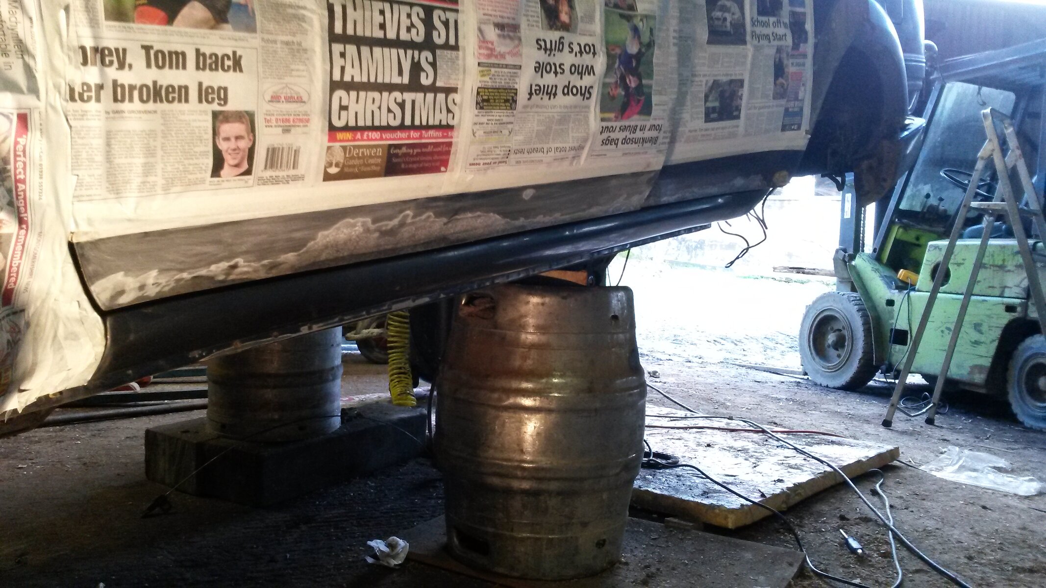
20141224_142143.jpg
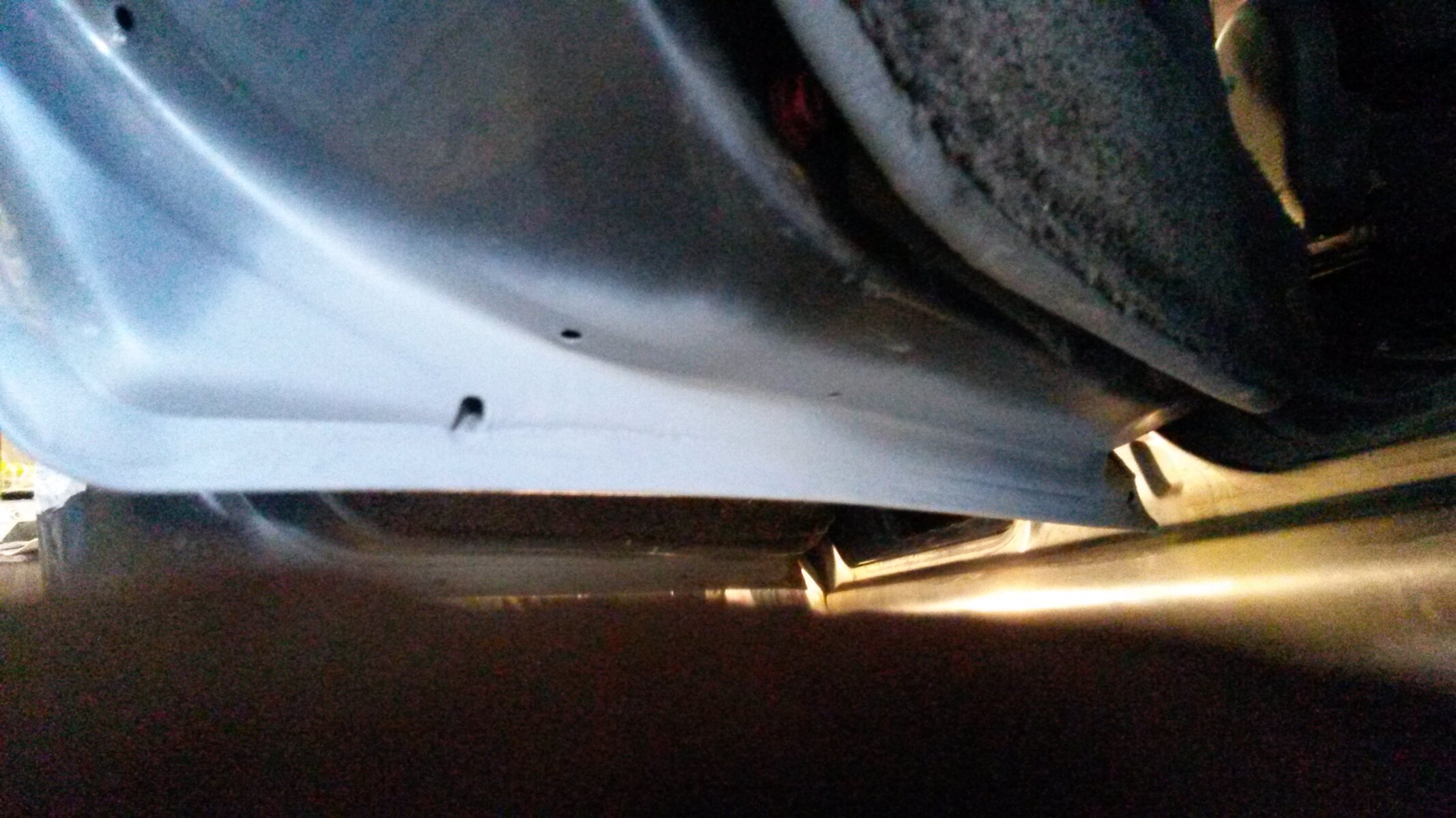
Had a mission tackling the rust issues on the doors yesterday. Passenger front was the worst..
20141224_145146.jpg
Used a spaghetti wheel in the grinder to take the metal down to clean. 2 good coats of etch primer then a good coat of high build primer. A bit of time with the block and should be nice and level..
20141224_145224.jpg
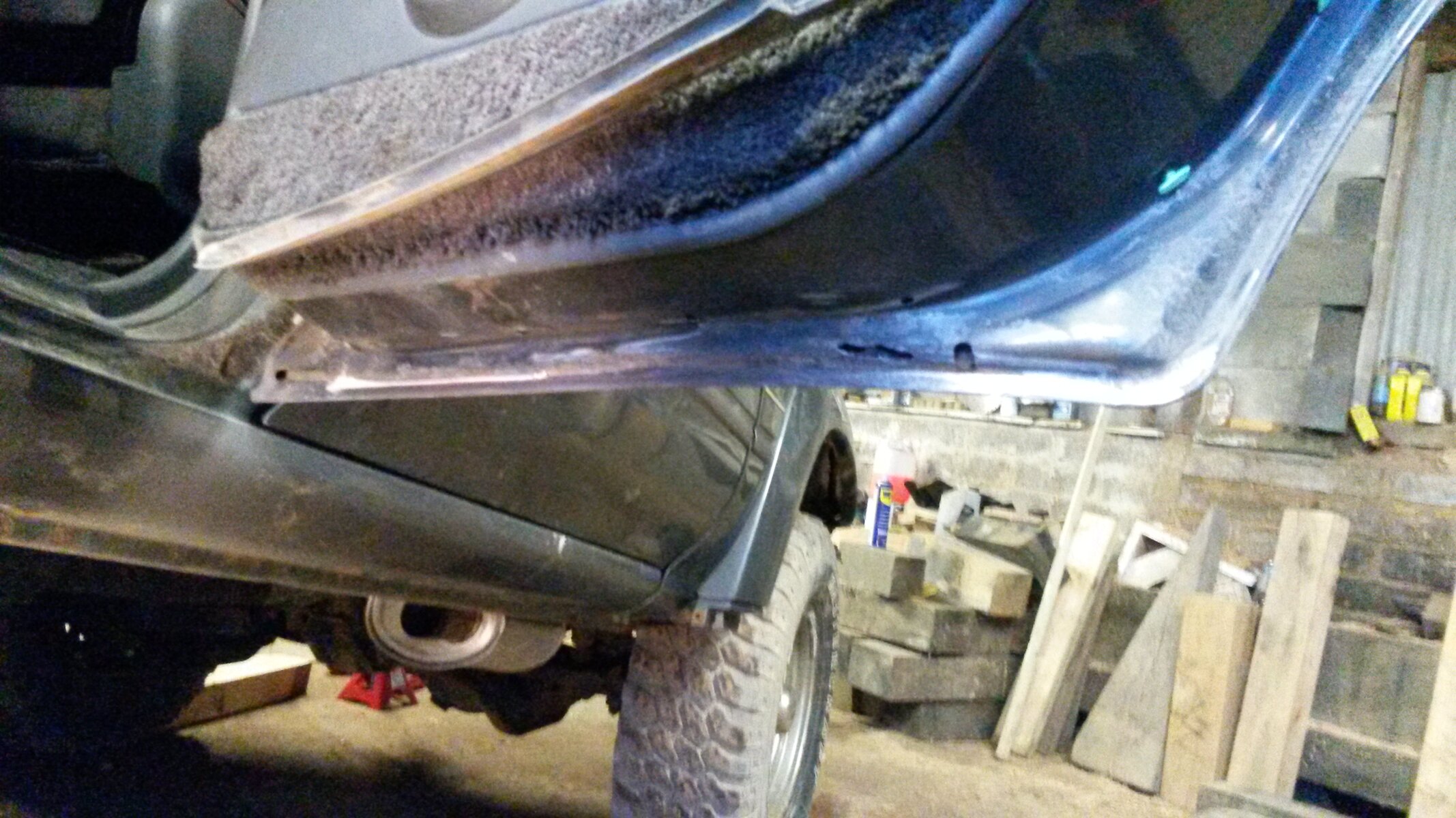
A bit of surface rust on the lower inner edge.... wouldn't be long until it looks like a 60 series door (bad).
20141224_154737.jpg
Good to catch this early.
20141224_154746.jpg
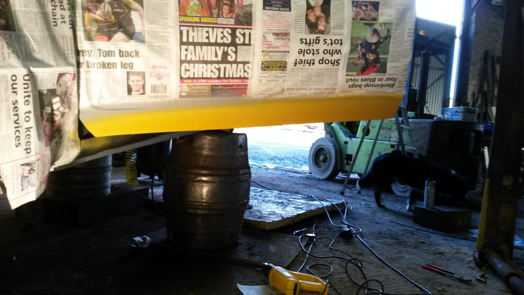
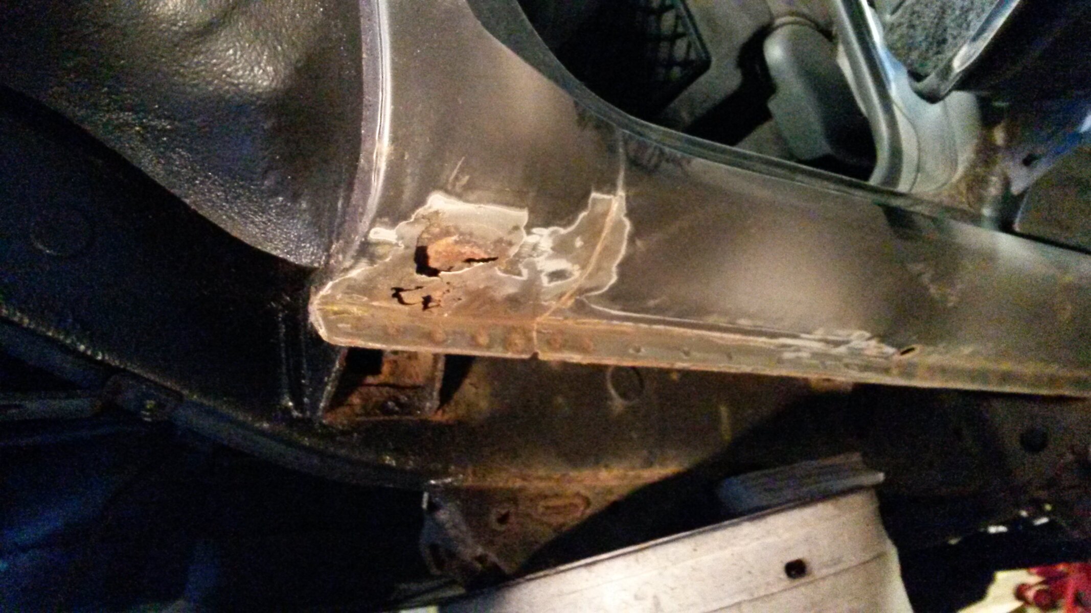
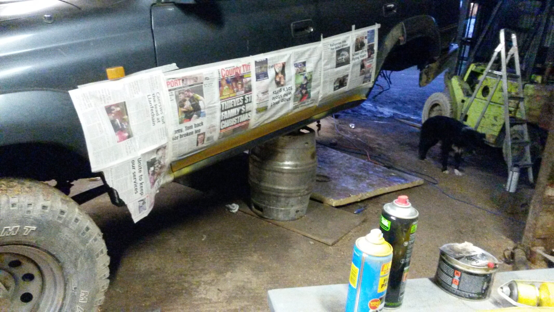
Nasty hole in the cill on the drivers side.. In fact the cills have quite a bit of surface rust on them. So will clean back to clean metal and coat with stone chip, a layer will help prevent rust returning. The cills are going to have a fair bit of wax oil in them after.

I'm thinking of respraying the truck in jet black. But am thinking is it possible to get a black interior for these and are they easily available?

Cheers all
 

Attachments

  • 20141224_162046.jpg
    20141224_162046.jpg
    2 MB · Views: 211
The link below shows the 80 standard front prop shaft which is out of phase with flanges on different to parallel planes. 26.9 diagram 3.

http://what-when-how.com/automobile/universal-joints-automobile/

I also understand that if one plane of a flange is turned at an angle, then another angle ( for example a horizontal vertical axle flange at right angles to the chassis and a gearbox flange pointing down wards and also to one side) vibration can be overcome by turning the two halves of the prop shaft sliding joint by just a few splines. That would be somewhere between in phase and out of phase.
 
Back
Top