Don't like the adverts?  Click here to remove them

Speedometer/Odometer not working but Speed sensor OK.

ByronJ

Well-Known Member
Joined
Jul 7, 2012
Messages
349
Country Flag
wales
My 1994 80 series has just failed its MOT because the speedometer is not working. No speed displayed and the odometer does not turn. Assuming it was the Hall speed sensor I bought a 2nd hand one and swapped it in. Still no speedometer!

So I did what I should have done in the first place and tested the sensor.

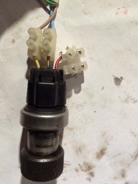
The sender is pretty easy to test. There are three connectors coming out of it. Using the colours on the wiring harness, yellow is the +12v supply, brown is earth and the red with green strip is the signal wire. Utilising an old plug and some screw connectors as below I supplied 12v and put a meter from the signal wire to earth. Slowly turning the armature I was able to detect 12v at four positions per revolution with the replacement and original sender.
 

Attachments

  • SpeedSensor.JPG
    SpeedSensor.JPG
    38 KB · Views: 3,433
Last edited:
Non functioning peedometer, checking PCB

So I stripped out the dash to check the PCB on the back of the speedo like Starcruiser's the top of the PCB was blackened.
SpeedoDirtyPCB.JPG


However after cleaning it up the tracks appeared to be intact. Which, I guess, is not too surprising considering the odometer is not turning over either.

SpeedoCLeanPCB.jpg
 
Non funtioning speedometer. Location of signal wire at instrument cluster?

Despite studying the wiring diagram in the FSM I cannot locate where the signal pulse enters the instrument cluster. I would be most grateful if someone would shed some light on this so that I can try a continuity test.

Tomorrow I hope to locate the signal wire behind the glove box and check for continuity to there and if ok try and trace that wire to the instrument cluster. The problem is made more complex by the after-market immobiliser which has hacked into the loom behind the instrument cluster and inserted undocumented bits between some of the wires attached to the back of the speedometer. That said the immobiliser appears to be working correctly.

Any suggestions as to what the problem might be and how to locate it would be most welcome.
 
Last edited:
Are you certain there is not a crack in the second track down , above and to the left of the solder blob above and to the left of the component marked 102. Test across for continuity.
 
Otherwise, try each of the fixing screws for continuity to your sender plug, only those on the PCB though as the others only work the cam belt light.
 
They cannot fail the car if the speedo does not work. It has to be illegible, obviously damaged or not illuminated.
 
Don't like the adverts?  Click here to remove them
Speedometer is a testable item for MOT

They cannot fail the car if the speedo does not work. It has to be illegible, obviously damaged or not illuminated.

I wish that was true. Apparently the speedo has been a testable item since 2012 :icon-cry:

According to the AA:

"The car will fail if a speedometer is not fitted, is incomplete, inoperative, has a dial glass broken/missing or cannot be illuminated."
 
Continuity test.

Otherwise, try each of the fixing screws for continuity to your sender plug, only those on the PCB though as the others only work the cam belt light.

This afternoon I carried out a continuity test from the signal wire on the sender (green with a red stripe) to the screws on the back of the speedo. I got some low resistance readings but not clean continuity. There are three wires attached to the back of the speedo which I assume are part of the after-market immobiliser.

WiresOnBoard.jpg

These wires run to a small black box and a further wire runs from this box to the loom.

At the loom I found two wires had been cut, soldered together and joined to a fourth wire leading to this little black box. I found full continuity from the cut wires back to the signal wire.

HackedPlug.jpg


WiresCutAtPlug.JPG

The cut wires are Brown/Black and Red/Green (bit of a clue there). These correspond with two wires cut from the connector into the back of the speedo. So I removed the little black box and reinstated the wires back to the plug and now I have full continuity from the plug to the sender.

Feeling very optimistic I went for a spin but still no speedo :icon-cry:.

Now I will check (where I can for continuity on the instrument cluster.

PS. My '91 cruiser has manual input into the speedo so I cannot swap parts around :doh:
 
Last edited:
Right. I did not realise they checked the speedo if it appeared OK. They would have to have the wheels turning, presumably on the rolling road, but I don't think my tester bothers looking at mine. It does work though.

It does look like that your PCB board may be faulty as SC says.
 
Is this my old one Byron ? I know on the imports there's a gizmo on the side of the gearbox that converts KPH to MPH. might be worth exploring.
 
Yes, as JM says there's a little gearbox which (if you have one) can be removed if necessary, however I cannot imagine how that could fail.

Some checks you could do…

1, check to see if the odometer works while the speedo doesn't. I found mine after the needle stopped for bore than the usual 400 yards and saw the counters turning. Test across the tracks on the PCB.

2, Run your test wires to the test plug you made up and have that fitted to the vehicle while you go for a spin and see if you get the same pulses.

3, Check from that plug where the wires were cut (that wasn't an immobiliser BTW) back to the terminals on the back of the speedo. (I can only think it was some sort of gizmo to counteract the speed difference of larger tyres, unless it was the way they converted Kmh to Mph instead of the little gearbox.
 
Last edited:
Is this my old one Byron ? I know on the imports there's a gizmo on the side of the gearbox that converts KPH to MPH. might be worth exploring.

Hi Brian. Yes this is your old cruiser. The car is a pleasure to drive so this speedo problem is a real pain as no MOT no Drive :eusa-naughty:. There does not appear to be any gizmo on the gearbox. In fact (like SC) I think the bits I removed from behind the speedo were to convert KMH tp MPH.
 
That's pretty much certain given no gearbox on the sender. Though removing it hasn't solved your problem so more testing to be done I believe. It looks as though it's all present up to the back of the speedo (unless I've missed something) so it's looking like a break on the PCB to me (though I may be jumping the gun a bit) if everything checks out to the screw terminals on the back then it's got to be in the speedo itself.
 
Some checks you could do…

1, check to see if the odometer works while the speedo doesn't. I found mine after the needle stopped for bore than the usual 400 yards and saw the counters turning. Test across the tracks on the PCB.

Neither the odometer or the speedo work. I checked continuity on the PCB as you suggested but all seems in order.

2, Run your test wires to the test plug you made up and have that fitted to the vehicle while you go for a spin and see if you get the same pulses.

I am unable to measure the pulses if the sender is spinning fast as they are momentary. But I have tried both senders on the car and also connected the signal wire directly to the back of the speedo and spun the sender with an electric drill with no reaction. It feels as if there is no power to the speedo at all or it is totally jammed so is unable to react to the sender's pulses. But I have not found a way to check that as the board is only powered when plugged into the loom and then the rear is not accessible :icon-rolleyes:.

3, Check from that plug where the wires were cut (that wasn't an immobiliser BTW) back to the terminals on the back of the speedo. (I can only think it was some sort of gizmo to counteract the speed difference of larger tyres, unless it was the way they converted Kmh to Mph instead of the little gearbox.

I have checked continuity from the sender to the plug and on to PCB board and all seems well :icon-cry:. As you suggest I now think the bits I removed were to force the speedo to work in mph rather than kph.

Thank you for your good suggestions. I am coming to the conclusion that the speedo is the most likely culprit. I have spoken with Karl and he is going to post me an instrument cluster on Monday. I will swap that in and see what happens.

I have been thinking of testing the speedo in isolation but it appears to have 6 connections so not sure where to begin! If anyone has any ideas or suggestions please feel free to pitch in. All input will be appreciated.
 
The major wires needed and concerned with the speedo should be the ones the black box tapped into.

The binnacle swap from Karl or even just the speedo will probably be the simplest way to go. You may even get the speedo to work in Mph as it is in the speedo not the sender that this is different (I believe, as there is only the one sender) unless I've been given the wrong info.
 
Last edited:
Speedo Now Works

I now have a working speedo :icon-biggrin:. Karl posted me a full instrument cluster on Monday and it arrived late Tuesday afternoon :icon-cool:.

I popped the cluster in took a short drive (I live on a private road - well a rough lane really :eusa-shhh:) and the needle moved :clap:. For whatever reasons some parts of the cluster did not work (Karl had already told me he was sure the speedo worked but was unsure about the rest).

So I swapped the speedo into my cluster and got my MOT at 09:30 this morning. An hour later the car was taxed and we were on our way to Cardiff airport.

The speedo is also working in MPH so I don't need the gizmo that was attached to the back of my old speedo :cool:.

Thanks for the helpful suggestions guys and thanks to Karl for helping me to get me back on the road quickly :thumbup:.
 
Last edited:
Back
Top