Don't like the adverts?  Click here to remove them

Yet another 80 build thread

The ones on the back of tractor units HGVs are bright zinc plated so have corrosion resistence whether you can get smaller ones from motor factors i could not say one other choice would be hydrolic connectors as used on mini diggers as they are exposed to the elements most of the time as for protection for the fittings you can try and make your own from some over sized hose or see what comes with the fittings put one in the engine bay and rear one in a cubby hole in the back end brain now drained of ideas and me tea is ready
 
I know you know electrics well Steve so I won't teach to suck eggs here but the drop over that distance is quite a bit so the cabling will need to be suitable. I'm not an electrics genius but when I wired mine up, I actually tried linking it with different sized cables to see if it's all bollocks or true. I was staggered at how cable diameters strangled the pumps. They pull 40 amps I think and the supplied cable was about the max I could use before anything of the same size added to it started to heat up. Hopefully you'll be close enough to your miniature nuclear power pack.

There are grommets through the corners of the vehicle where the sun roof drains. You could go through them.
 
Steve, I like your battery. A 120Ah Li based battery should provide at least the same amount of energy as 150Ah lead based battery. The BMS is of course mandatory for safety as any Li based battery may catch fire when overcharged or underdischarged. But you got me wondering about the balancing of cells. Lead acid battery cells will balance automatically when charged over 2,4V (6x2,4=14,4) so keeping a lead acid battery at 14,4 or 14,5V will result in balanced cells. This is not the case with Li based cells, they could drift apart under influence of e.g. temperature gradients. Will the BMS fix this ? If so, how ? Is a special charger required ?
 
@SteveJB I'll take a look thanks for the info

@Chris I'm running 32mm / 0 AWG cable from the batteries at the front to my red arc at the back and running the compressor of the Lipo4 battery at the back. The red arc is maxed at 40 amps off the alternator when charging the lipo4 battery so that should be fine (well overkill). I noticed the little clear tube at the back just behind the rear lights and wonder what it's used for as I don't have a sunroof, I'll follow the tube and see where it pops out.

@PeterLC How the BMS works is that each cell as a cable to it, it uses each cable to work out the voltage of each cell and then has a resistor to discharge the cells if they become unbalanced. This means that all the cells should be balanced but if you have the same internal resistance the cells should discharge the charge at similar rates anyway. The BMS also has massive MOSFETs which is used to disconnect the cells on over voltage or under voltage or over current.
As the BMS is smart then you can use any dump charger that puts out over 14v but less than 14.4 really, as the BMS will balance the cells and disconnect the cells once it's charged. The problem is smart chargers have different charging phases that are not tailored to lifepo4 batteries unless you get a really new one. I can't see how these phases would damage the cells but I'm not an expert.
 
Well Steve, if the cells are out of balance, i.e. some voltages are higher than others when nearly full, applying 14,4V accross four cells will result in an overvoltage on the cell at high voltage, so the massive MOSFET will switch off the charger. As we are talking about LiFePO4, all cell voltages will become equal very quickly so balancing will stop although the cells are still at different state of charge. The massive MOSFET will most likely switch on only when you start discharging but at that point the balancing is still off and the cells are still not balanced. Balancing will resume only when the battery is recharged but then everything starts over. You need a very smart BMS to be able to accurately balance LFP cells. Would you mind sharing with us which BMS you rely on ? I would love to take a closer look.
 
Sure I've got two that I normally use,

https://www.aliexpress.com/item/32921460278.html?spm=a2g0s.9042311.0.0.449a4c4d1nFSBZ the 100amp common port one and
https://www.aliexpress.com/item/32963243885.html?spm=a2g0s.9042311.0.0.449a4c4d1nFSBZ is an 80amp separate port.

Common port BMS both charge and discharge is through one set of MOSFETS whereas the separate port versions have a set of charge specific MOSFETS and discharge MOSFETS, leading to two connections one for charge and one for discharge. The separate version is also Bluetooth so you can monitor it from your phone.
 
Don't like the adverts?  Click here to remove them
Well today has been a quick install as it started to p*ss it down:
20190831_180348.jpg

Thanks, @Roy Duffy for arranging believer of the lightforce lights, impressed with the quality of the wiring harness. Just got to find a way to get a few wires through the bulkhead for the light switch and the CB antenna now.
 
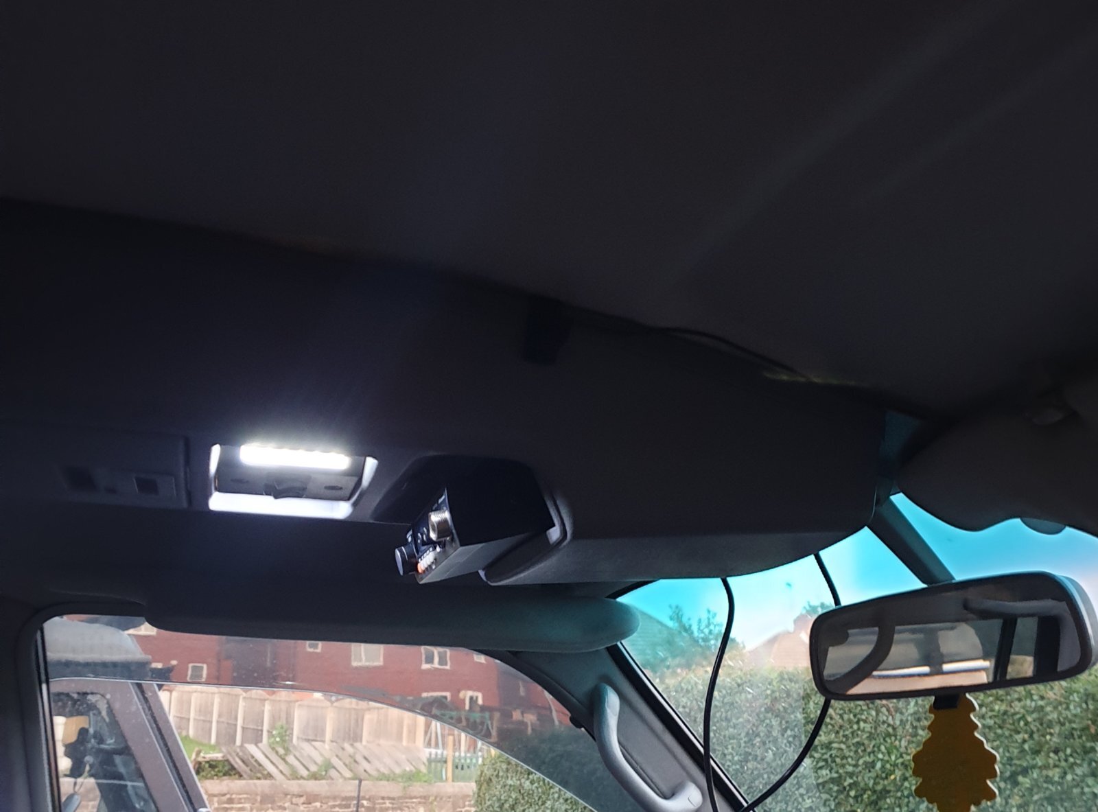
So even more jobs are done, thanks to @Trevor for pointing me at the best way to get the 25mm cable through the car. First thing, the outback roof console, it's so expensive but the perfect location for my CB and the interior lights are so much better.
20190901_200603.jpg
Super easy to wire up and looks amazing, now I had a CB I needed to fabricate the CB antenna holder, I'm going to upgrade the antenna but it's the only one my local shop had.
20190904_143621.jpg

Easy enough to fabricate out of some old metal and some pop rivets secured it to the bumper, next thing was to run some 25mm cable through the vehicle to the boot to my redarc charger.
20190907_161429.jpg

I ran it down the drivers side and into the rear, just need to wire in my redarc now.
20190907_161308.jpg
 
Last edited:
So some progress has happened but I've been super lazy with actually writing this up. After I ran the 25mm cable (overkill to run 80 amps), I got around for making to fuse / electric distribution board. It's made out of 2.5cm plyboard.
20190908_120438.jpeg


I made some brackets out of 2mm steel, with captive nuts on them to attach it to the wing and then went about screwing it to that. As it's so thick there isn't flex at all and it's very secure.
IMG-0120.jpg


With the RedArc installed there is enough space in the little window in the plastic cover to reset all the breaker and even monitor the status of the RedArc controller.

Once that was all set up, I need something to house my 130AH, so I got around to making/modify a set of draws for the back of the cruiser.

I created a simply draw structure out of the 2.5cm plywood, and glued and screwed all the joins.
20190913_181423.jpeg


Once that was created, I made some draws and dividers and went around covering the entire thing in vehicle carpet.
IMG_0076.jpeg


I've installed the main switch shutoff on the front panel that kills all the power to the front panel using a 40amp relay. The front panel has 2 cigarette sockets, 2 2xUSB and a 46w USB-c (which allows me to charge my laptop) the side has an Anderson plug on it to connect it to the RedArc. The front flap lifts up for access to the fusebox and all my recovery gear and the rear is for access to my 130ah Lithium battery and I've allowed enough space to add another 130ah battery in case I need it (I can currently camp for 7 days without a solar input). I added a Victron BMV-712 to allow to monitor my battery, and also control a few relays to cut off charging if the battery drops below freezing, as it could damage the battery.

I've got a few questions,

1) I've run the solar input wires up the rear pillar and managed to get them in the roof lining but wondering how people run them through the roof, I've been thinking about maybe running them through the rear windscreen washer grommet? This is also going to be a problem if I add an Alucab roof tent as that need power as well.
2) I'm thinking of adding an invertor and wondering if anyone has any recommendations looking around the 500w / 1kw mark?
 
Well after seeing @Richard Turner installation of an iso fix bracket, I thought I'd give it a go seen as we are expecting next month.
Getting the seat out isn't that bad, and taking it apart so your left with the bottom isn't that bad also. First things first weld on the bracket and give it a spray.
IMG_0161.jpeg

IMG_0162.jpeg


After that simply cut the seat cloth and edge to expose the iso fix bracket.
2C920C2E-622C-4480-A956-A8201C5034EA.JPG

And do the same again on the seat covers and install the iso fix base.
IMG_0167.jpg
 
Nice mod Steve. Never thought I'd be saying that to something like this lol
 
Looks good Steve. Can you get the seatbelt across the seat base as well, belt and braces? If you pull the seatbelt out to its maximum, when it retracts it turns into a ratchet, automatically locking.
 
The base is only isofix, no seat belt mounts at all but with about a foot of weld, I’m not worried about the bracket coming off.
 
I'm not doubting your welding Steve, its more to hold the seat itself down. At the moment it is held by the latch under the seatbelt recepticle. If you had the seatbelt plugged in and ratcheted tight it would also be held down to the body, on the door side of the seat by the lap part of the belt, and the shoulder strap would help reinforce the backrest being pushed forwards by luggage.
 
Didn’t think about that good idea, I’ll do that now. Didn’t even cross my mind about the seat folding, I’ll have it buckled under the base. That way it fixes both problem like you said.
 
I'm not doubting your welding Steve, its more to hold the seat itself down. At the moment it is held by the latch under the seatbelt recepticle. If you had the seatbelt plugged in and ratcheted tight it would also be held down to the body, on the door side of the seat by the lap part of the belt, and the shoulder strap would help reinforce the backrest being pushed forwards by luggage.
If I'm understanding right. Plug the seat belt in first, then fit the baby seat?
 
Back
Top