Don't like the adverts?  Click here to remove them

arduino & touchslide

Very impressive, is there much room on the arduino board to add anything else, assuming of course something else would be required?

If you don't connect up all the senders/sensors, I'm assuming it would just show an error but still work?
 
There is quite a bit of space on the interface board still which I put a grid of solder pads in as a mini prototype area for any slight changes or experiments. Some features are in separate plug in modules, like the real time clock, the EGT thermocouple interface (cold junction temperature compensation) and TPMS receiver board, any of which could be left off if not needed. It will work with only 2 wires (+ and -) connected but it will only show main battery voltage till you start to connect some more. Mine will be connected in stages not all at once but the ATF temperature sensor wire will never be connected for example :shifty:
 
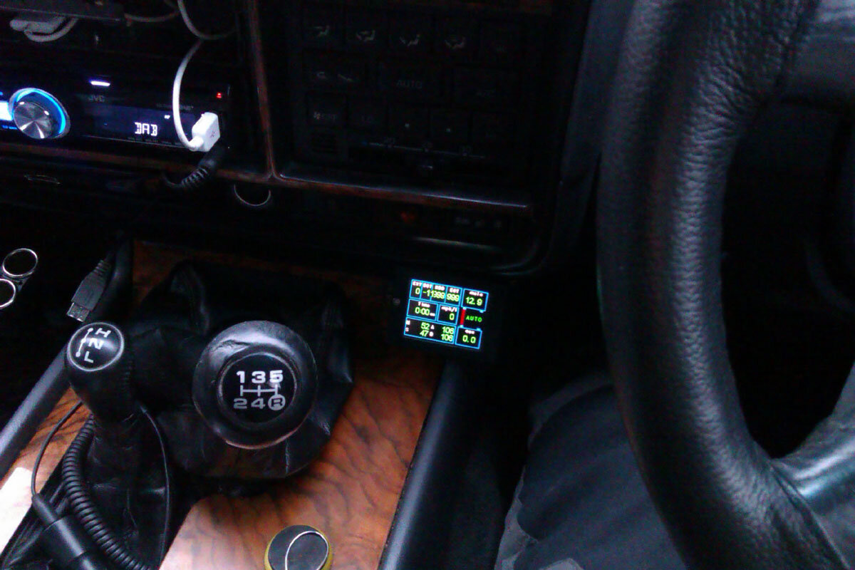
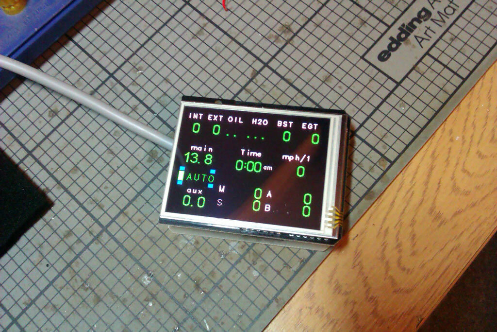
Stuck it on the centre console and wired up to the ever so useful power outlet in the engine bay so when I have a drive to the Electrics 101 tomorrow I can see if it's ok low down out of the way or needs to go higher up on the dash.
IMAG1363.jpg
 
Really keen to see this tomorrow JW.
Will it work on my ageing '92 ?
 
Last edited:
Most of what it does should work on anything but I don't know if your 92 may be cable drive for the speedometer? If it is then the trip / speed functions won't work as is. It'd be possible to add an extra pickup to make trip and speed display work but it still couldn't do speedometer correction, you'd have to swap to an electric speedometer for that if it's possible. Not sure when they switched from cable to electronic though, maybe it was very early and 92's are electronic?
 
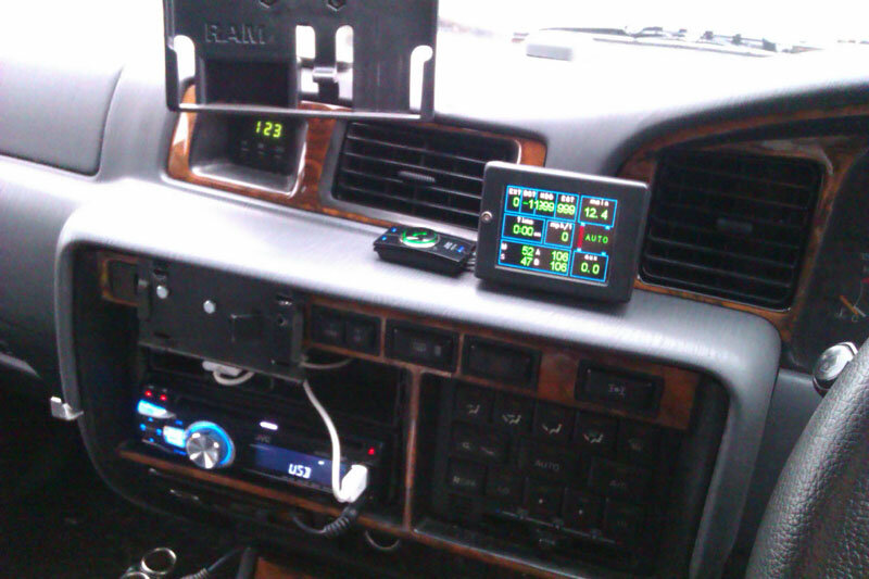
It worked ok down on the centre console for the occasional glance but it could have been better and I think if it started beeping at me to warn of e.g. coolant loss it might be a bit distracting having to look down so far to see what is wrong. Trying it up on the main dash now where it's not so discreet but is less distracting to look at.
IMAG1365.jpg
Time to start connecting it to the sensors.
 
Don't like the adverts?  Click here to remove them
80mmx60mm so about the same size as an IBS controller. Not quite as compact as the one Gav has in his 100 but not much in it.
 
Hooked up the speed wires in and out of the gadget when I had 15 minutes spare this afternoon. My 80 has the same connectors and wires as yours Richard so your pictures saved me figuring it out for myself :icon-cool:

Gav,

This is the connector you're looking for.
2011-04-01_1010562.jpg


I've labelled mine IG-1 so I can find it again. It's behind the glove box and on the 24V the ECU which you can see hanging down in the second pic

2011-04-01_1010563.jpg


This should show the type that you're looking for. Yellow blob is where I traced the connection from the speedo to in the loom.

IG1-plug.jpg


Not sure if it's the same on all models and I've seen mention that it's on pin1 on some vehicles. The easiest way to check is to disconnect the plug and also the connector on the transfer case and test for connectivity between the 2 points with a meter. After a lot of prodding I got a signal on pin 18. When I reconnected the loom and tapped into the wire I could see a voltage switching when I rolled the truck forwards.

Cheers
 
I do have to say that this little monkey is about the most useful tool in the shed on the hundee - JW will obviously upgrading Oiley's to the MKII as part of the ongoing support agreement :wtf:

MkI can go in Muxley!!! :shhh:

Seriously folks - you all need one of these without knowing it yet... :icon-cool:
 
It's only the interface board that needs upgrading on Oiley and a bit of reprogramming to bring it up to date.
 
Mounted the boost sensor and wired it in along with the coolant temp, coolant loss and fuel changeover lines. Waiting for parts to fit the oil pressure sender but the parts for EGT thermocouple cold junction interface are here so I need to get busy with the soldering iron and make that up.
IMAG1366.jpg

IMAG1367.jpg

Had a quick blast round the block and all seemed to be working.
 
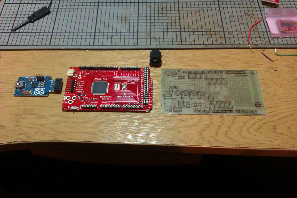
I've started making another one of these so I can test things out 'on the bench' without having to get the interface out of the car and then remember to put it back in again afterwards! I'm trying a variation on the Arduino board for this one and using a sparkfun mega 256 board instead which doesn't have an on board USB or external power socket which will make it a bit more compact.
IMAG1369.jpg
You can plug a USB to serial board in to program it still and just remove that when done. I got two USB boards so will leave one as intended for programming the Arduino and reprogram the other as a USB HID interface so the Arduino board can also pretend to be a USB keyboard. The reason for the USB keyboard part is I plan to make my steering wheel cruise control controls also control my PC, so I can zoom in and out, change maps, volume etc with steering wheel controls which is less distracting than the hand eye coordination required to press buttons on a touch screen suspended in mid air ...
 
I like the steering wheel control buttons idea. But it sounds quite a complex thing to undertake, but I am sure you will manage no probs. I wouldn't have a clue !
 
I had a look at trying to "copy" this project but on doing some reading on the forums I was lost in less than 5 min trying to understand what all the bits do and then after all that you still have to program it....count me out I just dont think I have the brain power for such a project.

I shall watch with much interest.
 
Like a lot of things, easy if you know how, hard if you don't :icon-biggrin: but as I was offering to build them for people all you need to be competent to do is connect it to the power and whatever sensors you want to use which are just standard ones and usually one wire per sensor. It's not a particularly cheap option if you add a full range of sensors but it's neat and tidy.
 
Like a lot of things, easy if you know how, hard if you don't :icon-biggrin: but as I was offering to build them for people all you need to be competent to do is connect it to the power and whatever sensors you want to use which are just standard ones and usually one wire per sensor. It's not a particularly cheap option if you add a full range of sensors but it's neat and tidy.

Hi Jon

As I am new here and haven't worked out how to pm on here yet could you pm with a price if you are still going to make these.
 
As I am new here and haven't worked out how to pm on here yet could you pm with a price if you are still going to make these.
If someone sends me a Touchslide and Arduino Mega 256 I will program them and then build an interface board for £25, to cover the raw costs of the interface board, not my time. That way if there is a subsequent hardware problem with say the screen, you can take it up with your supplier :icon-cool: There's no way I want to be dealing with replacing hardware that's been fried from being connected up wrong etc so I pass the buck back to you :icon-biggrin: It's very modular, if something breaks, unplug it and replace with a new one ... Gav hasn't managed to break his yet :shifty: The Touchslide and Arduino Mega 256 are only part of the cost, you can spend quite a bit on sensors depending how many you want to hook up e.g. the coolant loss sensor was something like £150 but is well worth it imo, boost sensor was not much change from £50, oil pressure sender is similar, temp senders are only about £10, EGT is probably pushing £100 with the probe and extra interface board needed to support it.
 
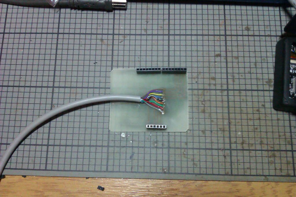
No stopping me now I cam make PCB's at will :lol: knocked one up this evening to plug the spare screen into instead of soldering wires to the pins directly and voiding the warranty :shifty: also been playing with the display layout a bit.
IMAG1373.jpg

IMAG1372.jpg

IMAG1375.jpg
 
Just connected the oil pressure sender and nice to see that there is good oil pressure :icon-cool: The OEM gauge / sender is a waste of space :doh:
 
Back
Top