Don't like the adverts?  Click here to remove them

Inverter project

warrenpfo

Well-Known Member
Joined
Jul 21, 2010
Messages
2,895
I was wondering where my 500w Mastervolt inverter might go today and then had a bit of a brain wave. I wont/don't want or use the cd shuttle and was going to remove it anyway so why not see if i can make it work.

I removed the centre arm rest and then the cd stacker and hey presto it does not fit in the original packaging.:wtf:

I then decided to take a look at the inverter and its construction and ended up stripping it down to the basic elements required and what do you know it is no bigger that the cd stacker and with a bit of majic will fit.

My question is how hot does the inverter get and would it be ok to mount under the arm rest seen as the cd stacker loading slot will act as a vent and i can/will fit an extraction fan n there if i need to but am concerned how hot the transmission tunnel may get and with the rear heater of that ducts to the centre console to keep the rear passengers feet warm will this also heat up the area too much.

Inverter vs cd stacker

8561950209_a244ef42fb.jpg

Inverter stripped on top of the cd stacker

8563054844_1c61ab4b37.jpg

Perfect size

8561942511_1685d3f03b.jpg


Inveter in the cd stacker mounting bracket

8561940933_588fdd239a.jpg
 
pretty sure the inverter manual said mount them vertically?
 
You are right it says mount them so that the cables come out the bottom but cant see any reason why you can mount it horizontally.
 
You are right it says mount them so that the cables come out the bottom but cant see any reason why you can mount it horizontally.
Heat flows upwards. It might be a question of the cooling fins getting the required air flow. It might also be that the built in temperature sensor is placed to feel the temp at the top of the enclosure, where the temperature is highest.
Not all inverters are made the same, but most modern ones emit very little heat when not in use. When under full load, the emitted heat could be e.g. 100 watts if the power is 500 W and the efficiency is 80 %. And that's too much for that small confined space.
If you could continue the modification of the inverter, it could be possible to mount bigger cooling fins on the power components, and of course a thermostatic fan would work wonders.
 
Thanks I will investigate and continue tomorrow.

An observation I did make was that apart from the one small fan the unit is suspended in its case and so only has the two cooling fins on the board to help cool it.

I do think this will work and will monitor it before putting the armrest part of the console back on.

it's out with the grinder tomorrow and ill modify the cd stacker case to mount the inverters guts and do not destroy the inverters case so I can always return it to its original working condition.

I have some pc motherboard mounts to space it off the backing plate and with a fan or two am sure I can make it work without you knowing its even there.
 
I would be quite worried about the running temperature of the inverter.

I don't think the inverter will be too happy stuffed away in a small enclosed area.

They need free airflow around them, to ensure long life, and trouble free.

Gra.
 
Don't like the adverts?  Click here to remove them
Progress to date:

The "case" (ex cd stacket case and mount) all fabed up and riveted together aloth with pc motherboard spacers to mount the inverter too.

8570071992_46143119de_z.jpg
8568970159_7d327f9a59_z.jpg

Inverter sitting in its case

8570063342_c0bd7d962a_z.jpg
8568960223_7e240b844b_z.jpg

Top flap mounted that the centre console bolts too fitted, its tight and ive had to cut a slot to miss the inverter but it fits like a glove thanks to my new toy.
8570052244_97846a83b8_z.jpg
8569046869_9f492848c9_z.jpg


Now for the next bit of the puzzle. To fit the inverter switch panel to the underside of the cd stacker face.

8568951063_cfe655bd57_z.jpg
8568945291_61726cdb73_z.jpg
8570037222_8cb05b7f6a_z.jpg

All going well it should fit back as it came out and you will be open to slide the cd stacker open to access the inverter controls.

8568935581_3fa56a63a0_z.jpg
8568932973_902e4019a3_z.jpg

All going well it should be a neat job.

I will mount it in place with out the centre console fitted to see how it fits and make sure it works and then monitor its heat output with the thought of mounting a nice and neat speaker grill on the passenger side of the centre console to vent hot air.

Time will tell and all this without making a single cut or change to the original inverter case so I should be able to put it back to its original condition if i ever want to sell it on or this does not work. Yes i wont have a cd stacker but i was going to replace it anyway.
 
Last edited:
I have a wiring diagram for the remote switch for those Warren. You don't need the controls exposed. You can do away with the controls all together. Sorry, should have said earlier.

A few cautions though, I have a couple of the 500W running in anger and they get very noisy and quite warm. They are forced-air cooling so I can't see orientation being a massive issue. If you put that in an enclosed space without fresh air, it'll shut down quite quickly, even at lowish loads.

As there is only one fan on it, it works hard to keep things cool. Running mine at full tilt causes it to scream. About 200W is staring to get noisy. These are also "breathing" cold, fresh air.

I don't think a speaker grill on one side will work - You need forced over the heatsinks as well as a fan to remove the air from the cavity. You'll also need a a hold on the other side to let fresh air in.
As you've taken it out of the box, the fan is no longer forcing air along the heatsinks. It'll just waft away causing the far end to get quite warm. Depending on where and how it measures its own heat, it may not see this as a problem and not trip out.

Finally on safety - you're messing with 230V AC there - At best you could short out the low side and hopefully pop a fuse at worst, you'll raise the chassis to 230V with some weird loop and make you dance.


The good thing about them is they do shut down if they overheat and reset when happy.
 
Last edited by a moderator:
Cheers Crispin, a few questions/thoughts.

The inverter case as std has the board mounted to it directly with no insulation and then you mount the case to the vehicle so I have applied the same thought process to the case I have mounted it too as I was worried that the board it directly mounted to the car in theory all be it at the mounting point on the pc board and spaced from the metal. I will give some serious thought to my cable run from the 230 point.

I will get someone at lincomb to cast there eye over the whole setup prior to firing it up for the first time.

I have not given much thought to the air flow/draw part of things but cant see the space its in being any smaller than the box it comes in but appreciate it will need some source of fresh air pushed over it over and above the current fan on the board. As you say I might even need to add a fan to draw out hot air but looking at the box it comes in there are not as many vents as i thought there would be.
 
Last edited:
True, it is mounted on the same back plate that it normally is so that's fine - my concern is how exposed it is though. If you're careful, the it'll be fine.

As for the heat side of things, you will need a fan to move air out of the centre console - free flow will not work in this case if you running it as there the air will not (with any great effect) move out of the console.
There will also be a touch of thermal runaway as you'll be recycling the warm air over the heatsinks to try and keep them cool. It'll just get warmer and warmer.

As you've lost the "ducting" effect over the heatsinks, I wonder if there are some components on the board between the heatwinks which also relied on fresh air?

On the wiring side of things, that should be simple and easy to do. Make sure you have the correct size cable for the 12V side (remember, if it's a long run then you want to go for the "next size up" in cable)
The 230V side of things is simple - 2.5mm (or even 1.5mm) 3 core flex will be fine for the output side. Run that into a socket and you'll be fine.


The inverter generates 230V which can kill - it really is not something to muck about with. I've been shocked by 230V and 380V more times than I care to remember and it is never nice. I have also lost a good friend who only got shocked by 230V once and it killed him.


Come to think of it, I am not sure what PD those heatsinks are at. Can you see if they are grounded i.e. ar the screws holding them in going through the PCB and onto the ground plain (thick copper area on the PCB)
Touching a heatsink and the car's chassis could tickle....


edit:
wire it all up and put it in a cardboard box mock-up (fire extinguisher at the ready ;) ) and see how it goes. It'll give you an idea of cooling you might need.
 
Last edited by a moderator:
I think this is an excellent mod. If I was more comfortable with 230V, I would try something similar.
 
8569208299_56c4a39264_z.jpg
8569205911_fd8b4ace1a_z.jpg

They seem to be riveted on and the flip side shows they are straight to the pc board and not a copper strip i think

8570301306_11e1c18812_z.jpg
 
I was going to get a temp gauge and see what kind of temps we dealing with as it will be surrounded with plastic so might need some form of heat shielding but not sure. Time will tell i guess but the card board boc is a nice idea and maybe with someones help we can probe around a bit with a meter to check if any of the metal bits are caring any current at all.
 
I think this is an excellent mod. If I was more comfortable with 230V, I would try something similar.
Don't mean to sound like I am knocking it - on the contrary. It's given me an idea so curious to see how it goes. The 150 has a 100W inverter built into the boot. Lots of space where it is hidden so if Warren's works out ok, I'll be swapping the guts of the 150s for this idea :)
 
Should be fine Warren - the heatsinks look like they touching the back plate so will (should) be safe.


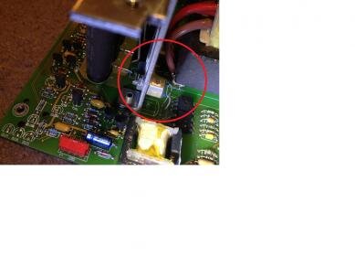
Here's your temperature sensor:
warren1.jpg
Seeing it is at the far end, it'll trip sooner.

The temps this will create would not be dangerous - it should cut out long before then. Probably around 50-60C I would imagine.
 
Crispin could you confirm the heat sinks should not carry a charge from the pictures posted? I wont hold you too it but just so i know if i need to modify the one mounting plate further or not. I wont be firing this up until i have an electric boffin with me or I'm at lincomb and can ask for some help.
 
Should be ok Warren. The first pic looks like the heatsink is against the back / bottom / top of the original case which is metal. That says they should be fine. Also the FETS (black things requiring cooling) are insulated.


If you wanted to pop round one weekend, happy to go through it all and give it a test run with you.
 
Thanks for the offer Crispin.

Would you know how I can extend the 6 or Is it 8 core ide cable that runs from the control panel to the board jumper.

The reason for wanting to use the original blue panel is that I'm not tire the remote panel has all the led indicator lights especially the overheat one... I may be wrong but it looked like it was just an on and off switch.

After further thought on the heat sinks I forgot to mention that the front face of the inverter case bolts to one of the heat sinks so it can't have a current flowing through it otherwise you would have a problem. Should have looked closer but it only twigged when I got into bed.
 
Last edited:
Back
Top