Don't like the adverts? Click here to remove them
You are using an out of date browser. It may not display this or other websites correctly.
You should upgrade or use an alternative browser.
You should upgrade or use an alternative browser.
LJ78 Build Thread
- Thread starter Ben
- Start date
- Joined
- Oct 13, 2010
- Messages
- 6,055
- Country Flag
OK...................
Wiring!
I wired all the switches, gauges and UHF in the roof console, on the kitchen table.

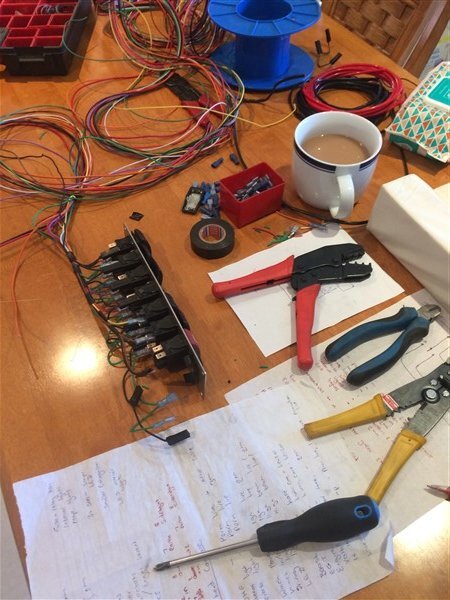
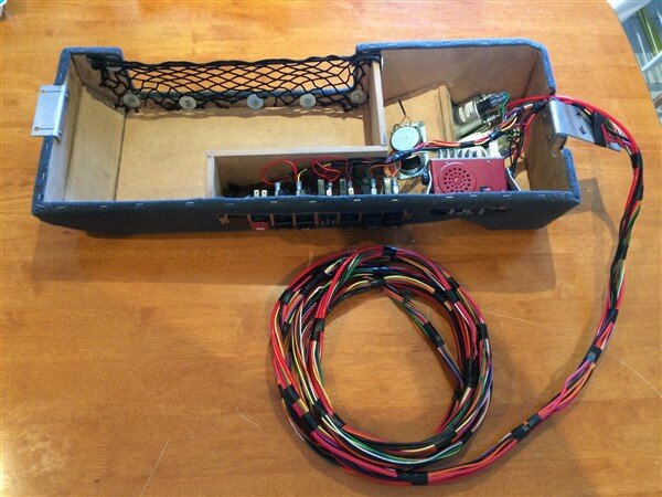
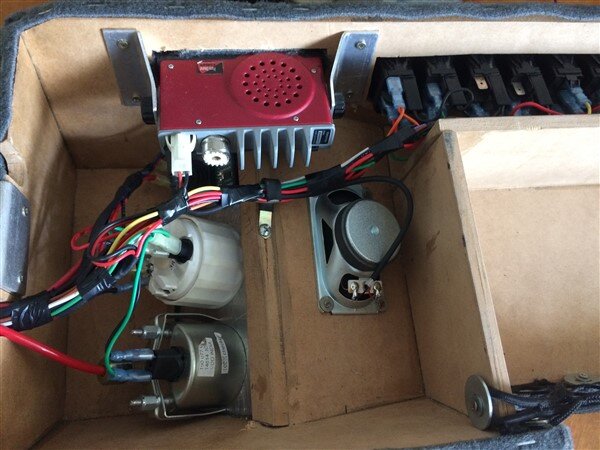
Then it was time to get all those wires in that loom from the underside of the roof to the engine bay.
I pealed back the headlining.........
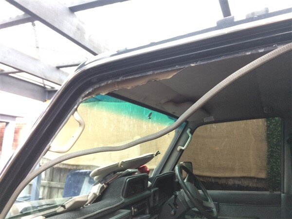
And dug out some hard plastic strip, which the auto electricians at work use for feeding wires through vehicles.
Its actually yellow tongue tongue, or in this case green tongue. For those of you not familiar with construction materials in Australia, our chipboard flooring doesnt come with a tongue and groove already machined into it like in Europe! No here it comes with grooves machined into each edge and a plastic strip that fits into these grooves in the boards, so basically a loose tongue.
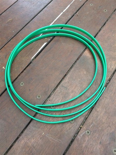
I fed this through a hole I made in the headlining and fed it through to where I had pealed the headlining down.
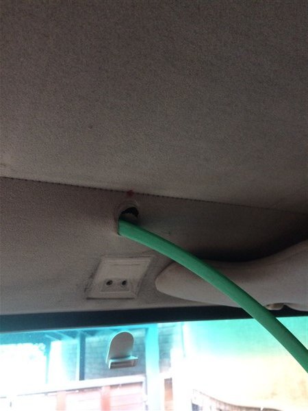
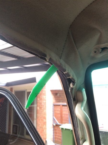
I then taped a rope and the UHF coaxle cable to it and pulled them through.
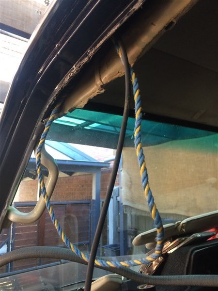
Next I struggled for hours trying to get first the green tongue down the A pillar and then a piece of stiff wire, like coat hanger wire.
Eventually the wire won and I was able to pull the rope through!
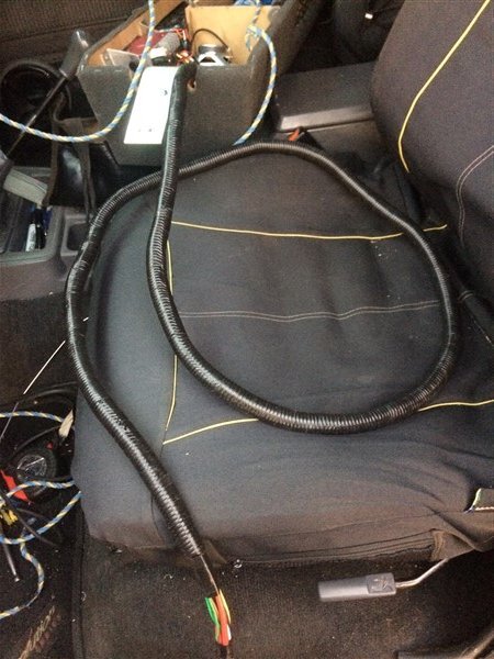
Next I covered the loom coming from the roof console in split tubing and taped it all up.
Taped the loom to the end of the rope and pulled it all through.
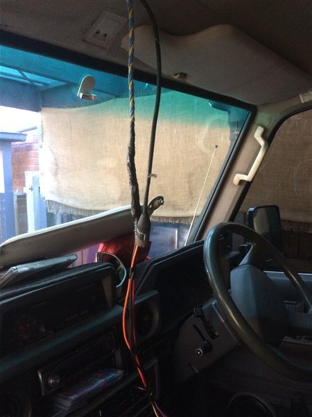
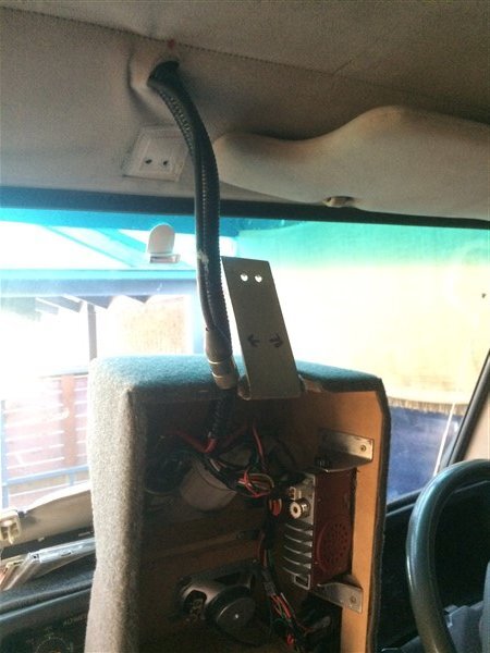
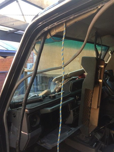
The roof console was soon bolted into position.
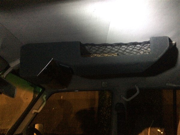
With no wires or cables visible!
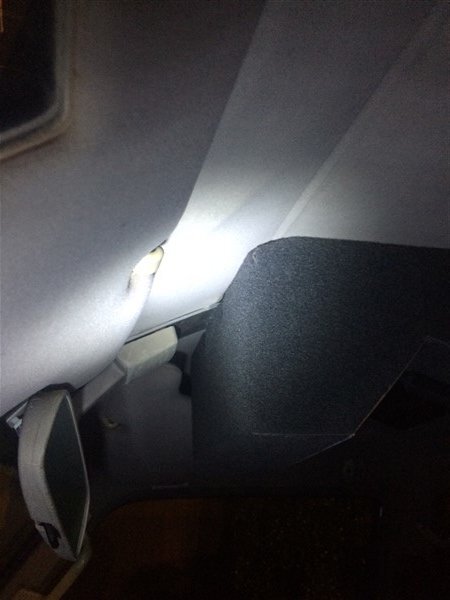
I left a piece of rope running from the roof down the A pillar just encase I have to pull anymore wires through in the future.
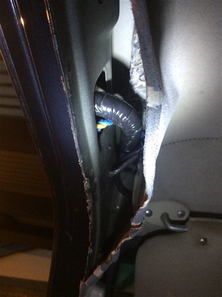
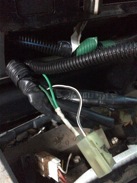
I had to cut some of the split tubing off the end of the loom at the base of the A pillar because I needed 2 wires from the loom.
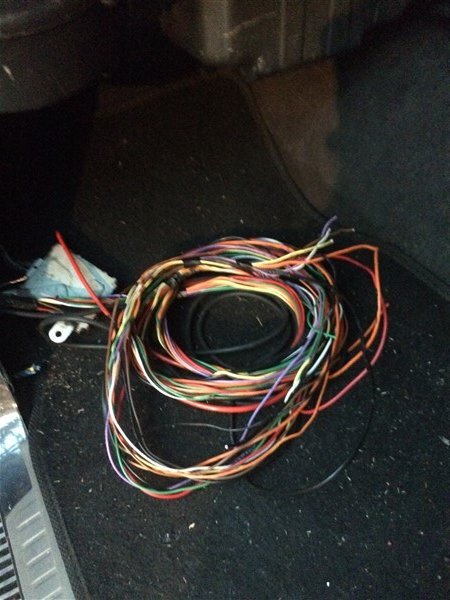
I pulled out a green 2mm and an orange 3mm.
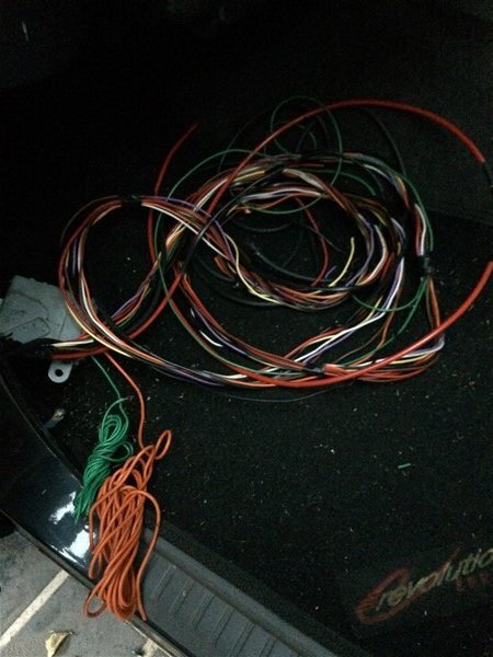
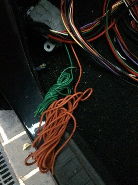
The green needed to be soldered to the the live wire going to one of the dash illumination lights, so that my switches and gauges also light up when the headlights/side lights are turned on.
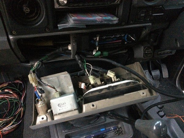
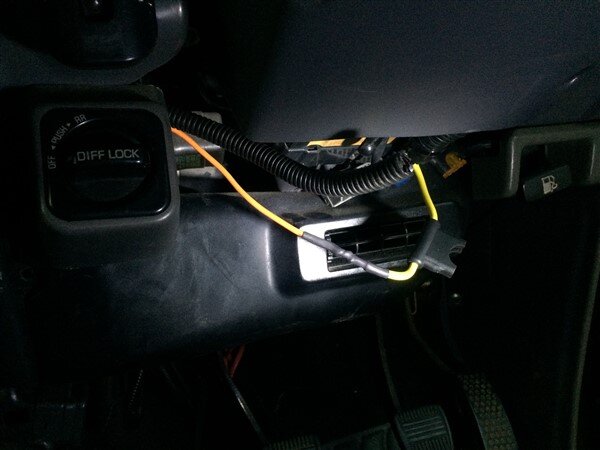
And the orange needed to go to an ignition live coming off the ignition, so that certain things like the gauges only come on with the ignition.
I wanted the UHF radio and light switches to be permanently live so that if there is ever an accident or the keys get lost we will still have a working UHF radio and lights.
The lights are also useful when setting camp up for example in the dark when you may not want to leave the keys in the ignition.
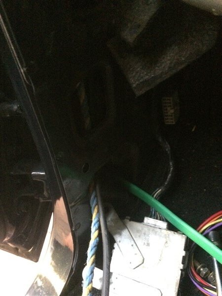
With those wires removed I taped the rest of the loom up in split tubing ready to feed it through the firewall and taped it to the green tongue.
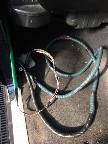
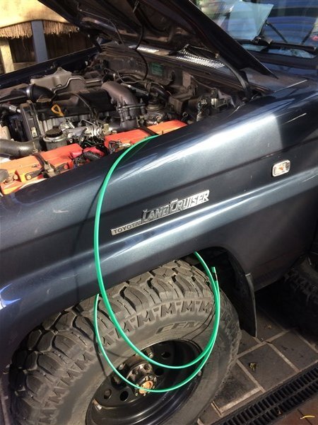
And pulled it through.
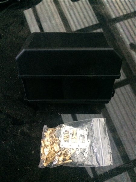
My fuse/relay box got delivered.
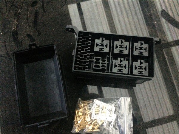
Next I needed to find a spot to mount it.
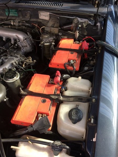
My only 2 options for mounting it on the passenger side were here next to the battery.
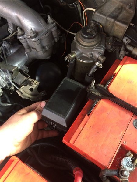
Which I wasnt that keen on, or here where the currently un-used headlight washer bottle was mounted.
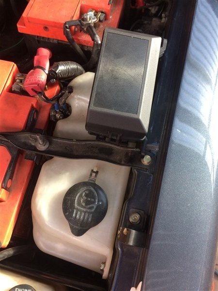
I decided I would loose the headlight washer bottle as both the pumps I had that mount on the bottom of the 2 headlight washer bottles I have, had both rusted out and a replacement from Japan isnt cheap!
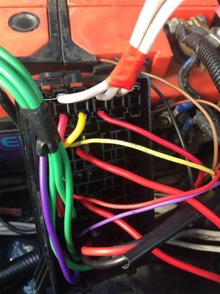
I wired up the fuse box and to add the positive feeds in I had to solder the 6mm wires on as they couldnt be crimped.
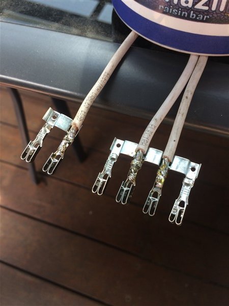
Thankfully the rest of the terminals were all crimp ones so much easier.
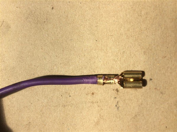
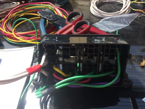
I connected all the wires coming down from the roof console.
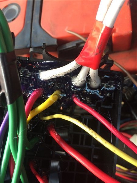
Then filled all the holes on the underside of the fuse/relay box with hot melt glue, to help secure everything.
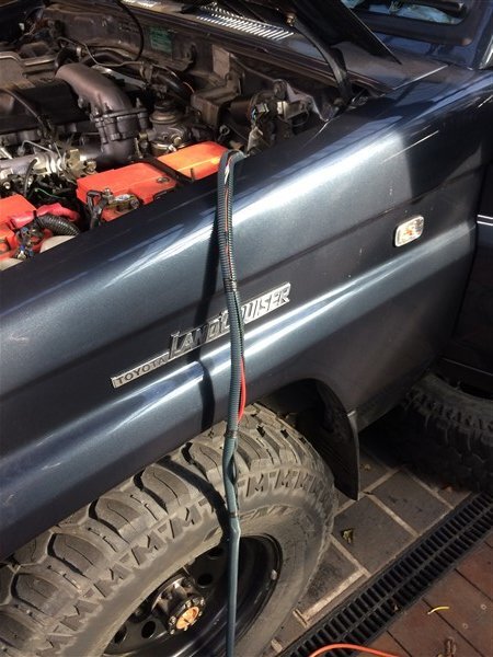
I ran the green tongue through the passenger side chassis rail, followed by some thick twin core cables that I will use for my rear LED lights in my bumper and a rear Anderson plug.
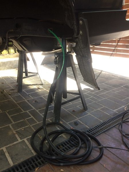
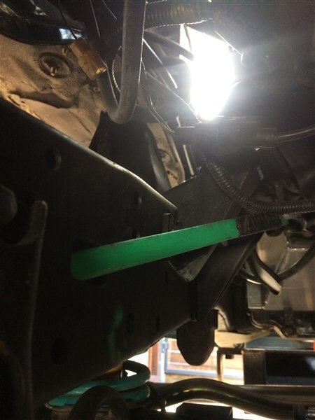
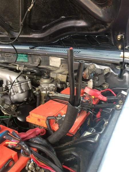
Sadly there was one spot where I couldnt get any cables through, so in this small section the wires had to run on the outside of the chassis rail.
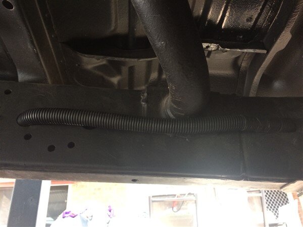
Pic limit reached, more soon.
Wiring!
I wired all the switches, gauges and UHF in the roof console, on the kitchen table.


Then it was time to get all those wires in that loom from the underside of the roof to the engine bay.

I pealed back the headlining.........

And dug out some hard plastic strip, which the auto electricians at work use for feeding wires through vehicles.
Its actually yellow tongue tongue, or in this case green tongue. For those of you not familiar with construction materials in Australia, our chipboard flooring doesnt come with a tongue and groove already machined into it like in Europe! No here it comes with grooves machined into each edge and a plastic strip that fits into these grooves in the boards, so basically a loose tongue.

I fed this through a hole I made in the headlining and fed it through to where I had pealed the headlining down.


I then taped a rope and the UHF coaxle cable to it and pulled them through.

Next I struggled for hours trying to get first the green tongue down the A pillar and then a piece of stiff wire, like coat hanger wire.

Eventually the wire won and I was able to pull the rope through!


Next I covered the loom coming from the roof console in split tubing and taped it all up.

Taped the loom to the end of the rope and pulled it all through.


The roof console was soon bolted into position.

With no wires or cables visible!

I left a piece of rope running from the roof down the A pillar just encase I have to pull anymore wires through in the future.

I had to cut some of the split tubing off the end of the loom at the base of the A pillar because I needed 2 wires from the loom.

I pulled out a green 2mm and an orange 3mm.


The green needed to be soldered to the the live wire going to one of the dash illumination lights, so that my switches and gauges also light up when the headlights/side lights are turned on.


And the orange needed to go to an ignition live coming off the ignition, so that certain things like the gauges only come on with the ignition.
I wanted the UHF radio and light switches to be permanently live so that if there is ever an accident or the keys get lost we will still have a working UHF radio and lights.
The lights are also useful when setting camp up for example in the dark when you may not want to leave the keys in the ignition.

With those wires removed I taped the rest of the loom up in split tubing ready to feed it through the firewall and taped it to the green tongue.


And pulled it through.

My fuse/relay box got delivered.


Next I needed to find a spot to mount it.

My only 2 options for mounting it on the passenger side were here next to the battery.

Which I wasnt that keen on, or here where the currently un-used headlight washer bottle was mounted.

I decided I would loose the headlight washer bottle as both the pumps I had that mount on the bottom of the 2 headlight washer bottles I have, had both rusted out and a replacement from Japan isnt cheap!
I wired up the fuse box and to add the positive feeds in I had to solder the 6mm wires on as they couldnt be crimped.

Thankfully the rest of the terminals were all crimp ones so much easier.


I connected all the wires coming down from the roof console.

Then filled all the holes on the underside of the fuse/relay box with hot melt glue, to help secure everything.

I ran the green tongue through the passenger side chassis rail, followed by some thick twin core cables that I will use for my rear LED lights in my bumper and a rear Anderson plug.


Sadly there was one spot where I couldnt get any cables through, so in this small section the wires had to run on the outside of the chassis rail.

Pic limit reached, more soon.
Last edited:
- Joined
- Oct 13, 2010
- Messages
- 6,055
- Country Flag
Heres the last of the electrics............
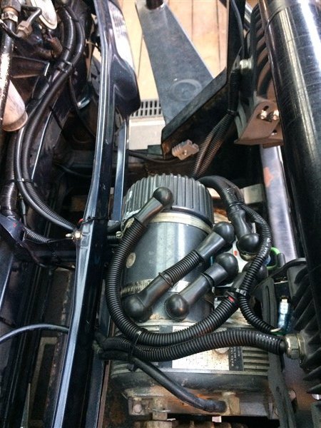
I decided to mount the solenoid on the winch motor to make the wires from the solenoid to motor as short and neat as possible.
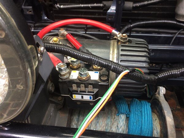
The blue pen marks are to show the orientation of the terminals that still needed crimping.
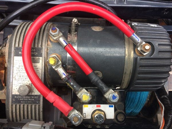
I took them to work and crimped them and heat shrunk them.
I also got some rubber boots to insulate the terminals.
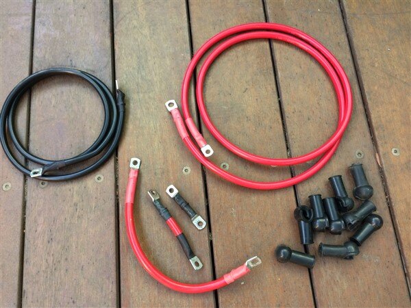
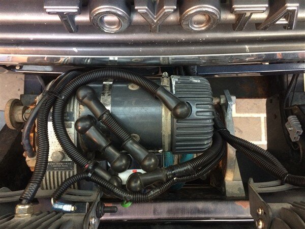
I removed the grill and wired everything up.
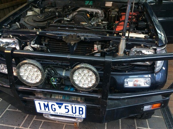
Lots of split tubing to help protect the wiring and make everything look nice and neat and professional.
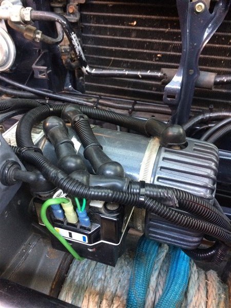
I dont use remote controls with my winches as I feel they are unnecessary on a 4wd.
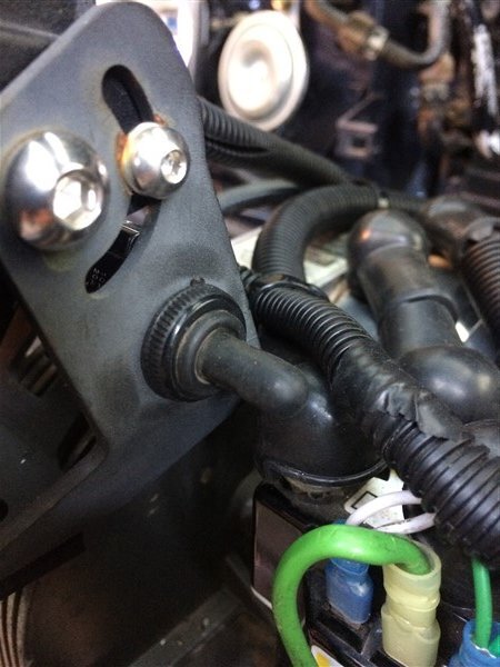
Instead I have an in/out switch inside the cab and an in/out switch on the bullbar as whenever I need to use the winch I'm either in the car driving and winching, or at the front of the car winding the winch in.
I mounted my in/out switch on one of my driving light brackets.
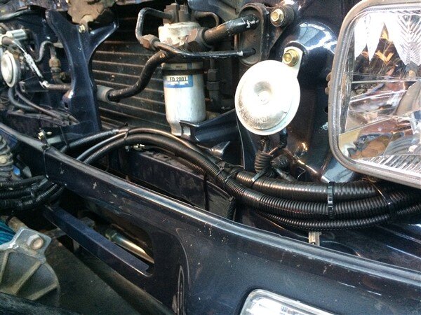
I secured all the wiring along the front of the rad support panel.
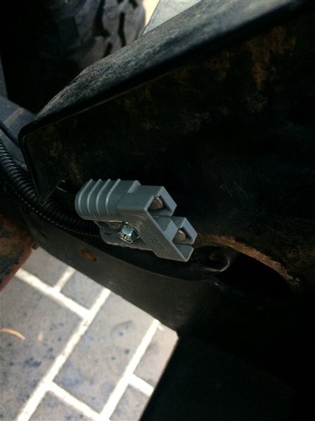
I added an Anderson plug to the bullbar.
This Anderson plug will be used for 3 things:
-Plugging my solar panel into for battery charging/running the fridge.
-Plugging my compressor/camp light into.
-Plugging my 240 volt battery charger into as I fitted an Anderson plug on the end instead of crocodile clips as it means then I can charge my batteries without having to lift the bonnet.
All done and grill back on.
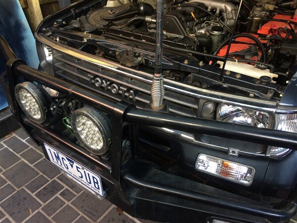
Beautifully neat winch wiring!
Rear diff lock actuator next........
I was convinced I had probably fitted the magnets wrong in the actuator when I rebuilt it.
So I decided to give it a quick test first.
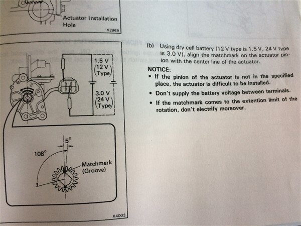
So I connected a battery to 2 wires and gave it a go.
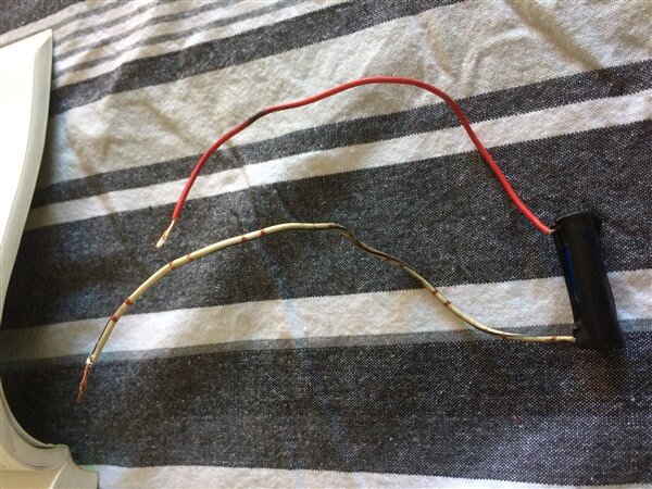
As suspected the thing didnt move.
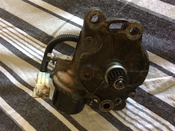
So I stripped it back down.
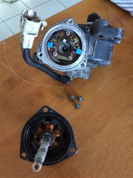
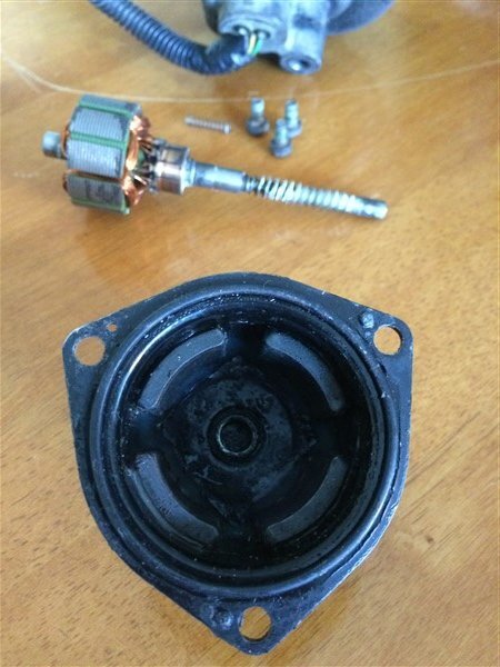
Removed the magnets.
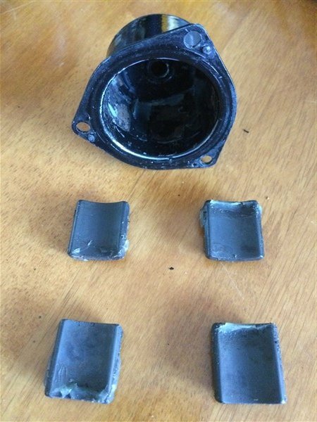
And it was pretty obvious which ones were North poled magnets and which ones were South.
As 2 of them spoon each other perfectly, but not the other 2 and vice versa.
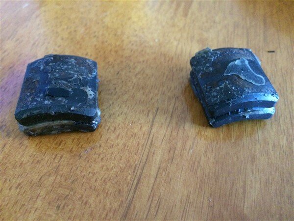
After reading this excellent thread on IH8MUD.
https://forum.ih8mud.com/threads/locker-actuator-rebuild.551069/page-1
I picked up some special grease that the guy recommends using.
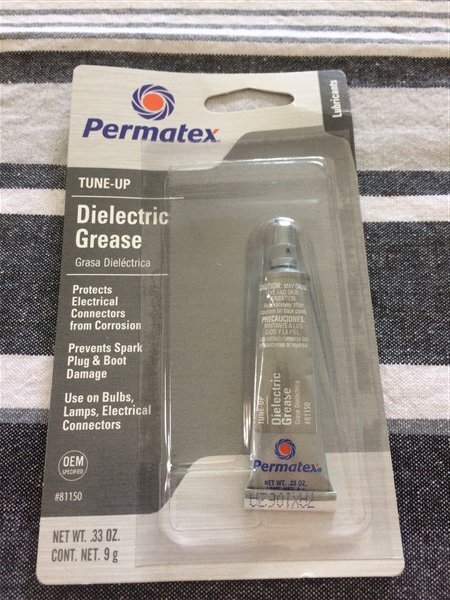
And using his pics I copied where the magnets should go because sadly I couldnt see any of the witness marks in mine as it had been so badly corroded.
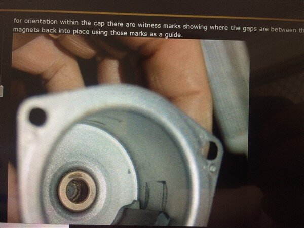
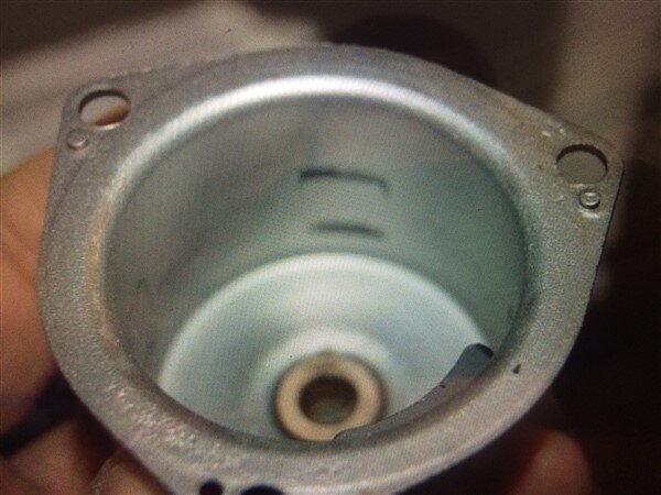
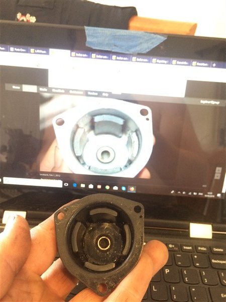
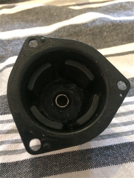
With my magnets glued in place it was time to reassemble it.
I particularly liked the guys tip of using the little wires on the brushes to help compress the springs that push the brushes out and hold them in while you push the motor shaft in.
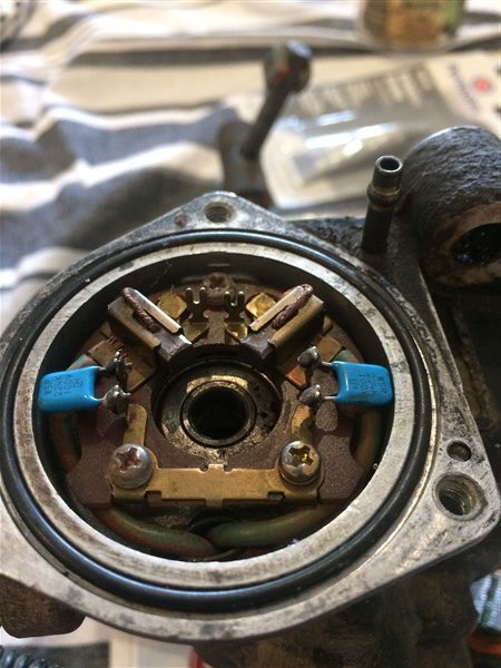
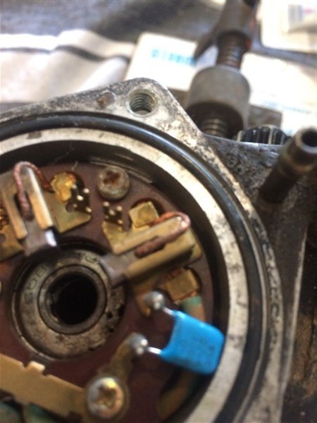
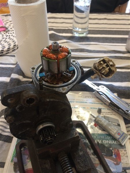
Sadly it still wasnt working with the 1.5volt battery so I decided to test it using the other technique of using a relay.
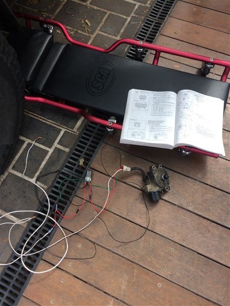
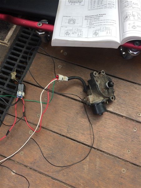
Sadly this proved unsuccessful too.
So now I need to decide whether I bite the bullet and pay the frankly ridiculous ($1k) price for a new one from Amayama/Megazip or whether I try and convert the existing actuator into a cable operated one.
I had some more deliveries.
Carling switch covers.
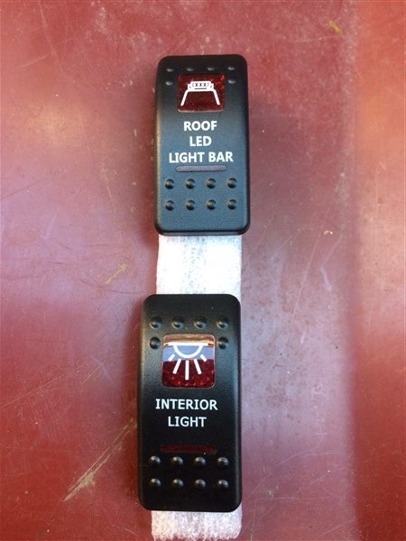
And LED interior strip lights.
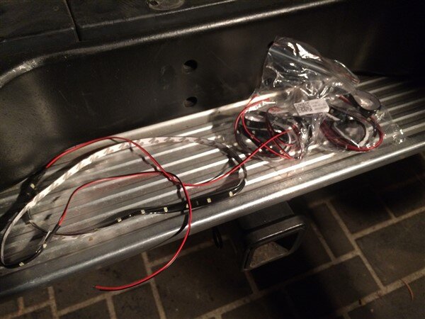
I had to swap some of the wires around for the switches as some of them were not illuminating properly.
A ratchet strap proved very useful for holding it up.
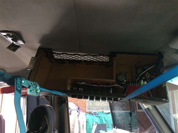
I had to refit the roof rack next so I could wire the LED light bar up.
*You will also spot the winch hook hanging out, more on that next update.
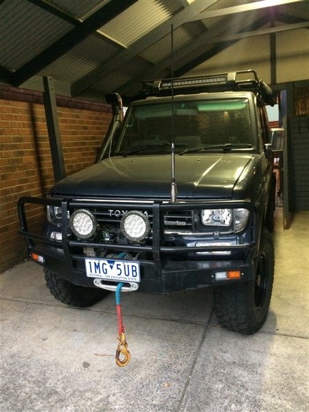
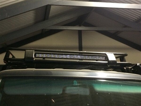
Once that was wired up the electrics were pretty much finished!
So this is how its all looking/working.
There is 2 unused/spare switches at the back of the switch panel, then the interior light switch.
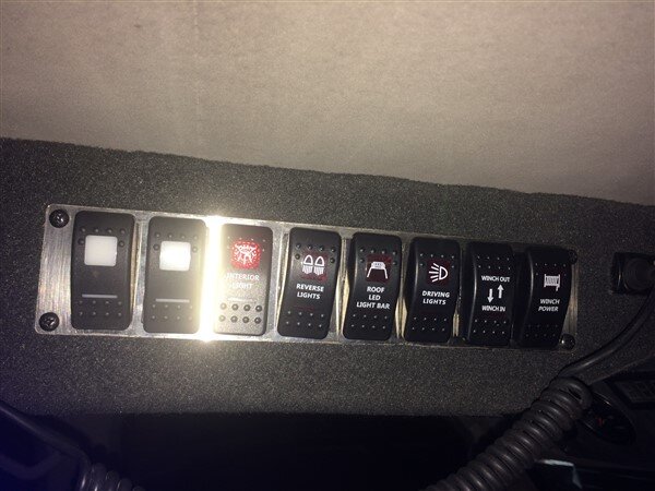
Which when flicked.
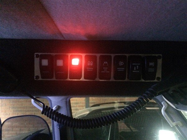
Lights the rear of the cab up nicely.
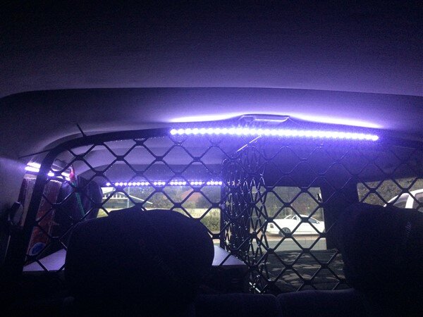
There is one 60cm forward facing one on the cargo barrier which lights the rear seats up perfectly.
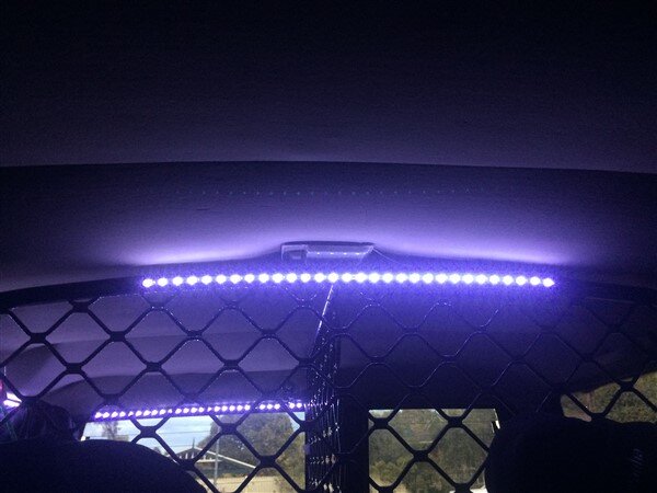
One side facing one to light up the area above the drawers where camping gear will be strapped down.
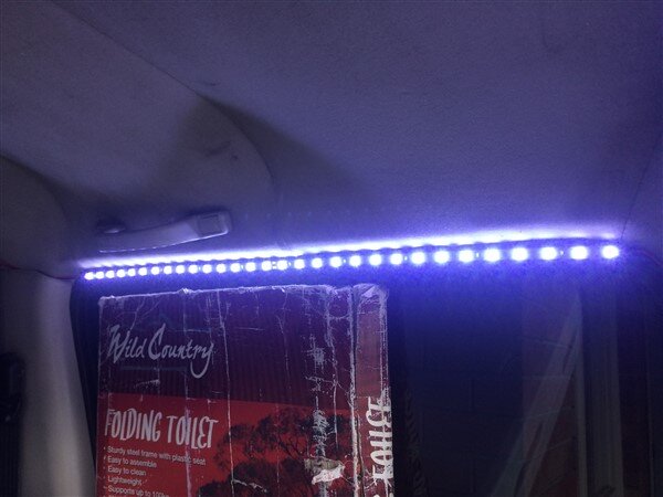
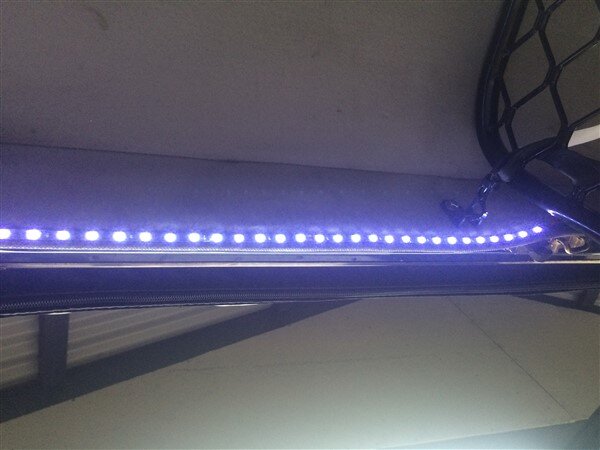
And another forwards facing one above the rear doors to help light up the drawers.
Next we have the rear lights/revers lights switch.
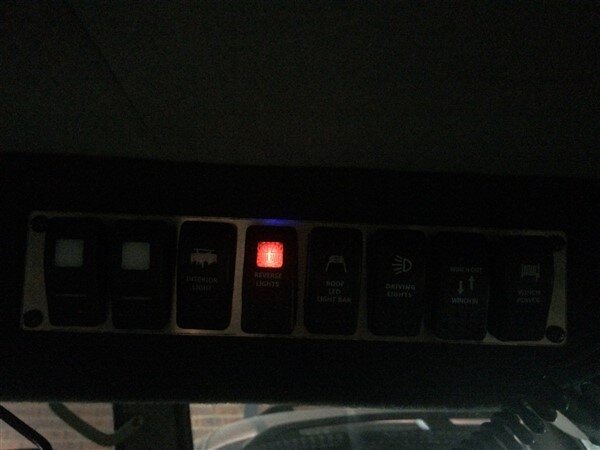
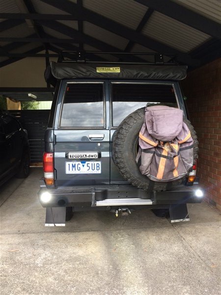
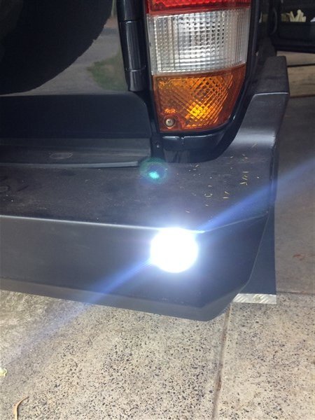
Followed by the roof LED light bar.
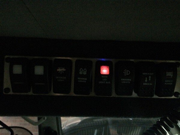
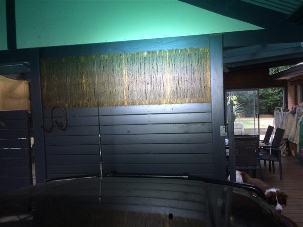
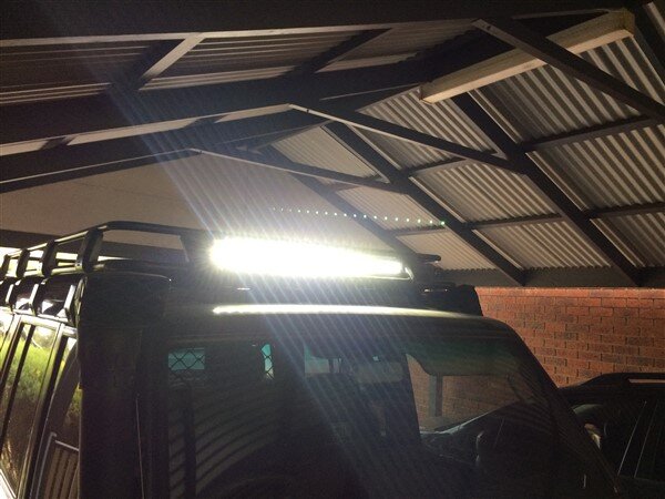
And the next switch is for the LED driving lights on the bullbar.
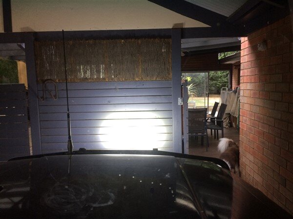
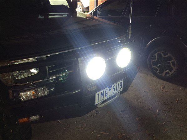
The final 2 switches are winch power and winch in/out.
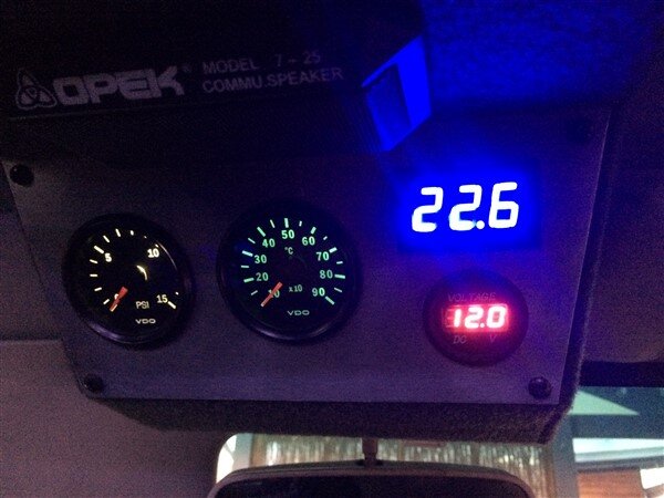
Then with the ignition and lights switched on the gauges all light up and work.
Boost on the left, then EGT then engine temp at the top (because the standard gauges are grossly inaccurate and by the time the standard gauge moves to red the engine has already overheated ) and below that is a volt gauge, which is very handy for keeping an eye on the alternator and how well its working!
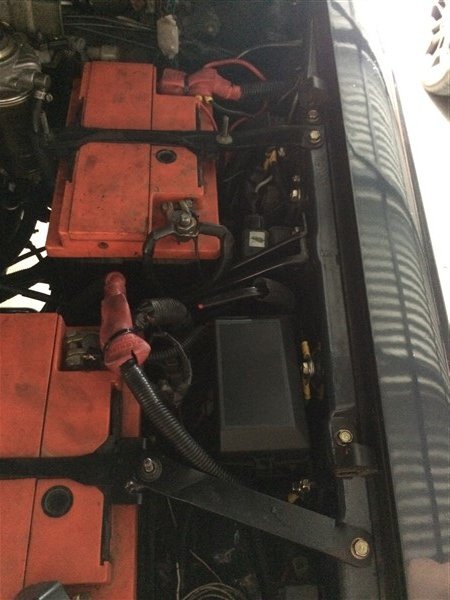
And one last engine bay pic showing the new fuse/relay box which bolted straight up to factory captive nuts on the inner guard.
And a new battery top mount I knocked up at work as sadly with the fuse/relay box there the standard top mount wouldnt fit.
I will try and get another update up in a day or 2.
I decided to mount the solenoid on the winch motor to make the wires from the solenoid to motor as short and neat as possible.

The blue pen marks are to show the orientation of the terminals that still needed crimping.

I took them to work and crimped them and heat shrunk them.
I also got some rubber boots to insulate the terminals.

I removed the grill and wired everything up.

Lots of split tubing to help protect the wiring and make everything look nice and neat and professional.


I dont use remote controls with my winches as I feel they are unnecessary on a 4wd.

Instead I have an in/out switch inside the cab and an in/out switch on the bullbar as whenever I need to use the winch I'm either in the car driving and winching, or at the front of the car winding the winch in.

I mounted my in/out switch on one of my driving light brackets.

I secured all the wiring along the front of the rad support panel.

I added an Anderson plug to the bullbar.
This Anderson plug will be used for 3 things:
-Plugging my solar panel into for battery charging/running the fridge.
-Plugging my compressor/camp light into.
-Plugging my 240 volt battery charger into as I fitted an Anderson plug on the end instead of crocodile clips as it means then I can charge my batteries without having to lift the bonnet.

All done and grill back on.

Beautifully neat winch wiring!


Rear diff lock actuator next........
I was convinced I had probably fitted the magnets wrong in the actuator when I rebuilt it.

So I decided to give it a quick test first.

So I connected a battery to 2 wires and gave it a go.

As suspected the thing didnt move.

So I stripped it back down.


Removed the magnets.

And it was pretty obvious which ones were North poled magnets and which ones were South.
As 2 of them spoon each other perfectly, but not the other 2 and vice versa.

After reading this excellent thread on IH8MUD.
https://forum.ih8mud.com/threads/locker-actuator-rebuild.551069/page-1
I picked up some special grease that the guy recommends using.

And using his pics I copied where the magnets should go because sadly I couldnt see any of the witness marks in mine as it had been so badly corroded.


With my magnets glued in place it was time to reassemble it.
I particularly liked the guys tip of using the little wires on the brushes to help compress the springs that push the brushes out and hold them in while you push the motor shaft in.


Sadly it still wasnt working with the 1.5volt battery so I decided to test it using the other technique of using a relay.


Sadly this proved unsuccessful too.

So now I need to decide whether I bite the bullet and pay the frankly ridiculous ($1k) price for a new one from Amayama/Megazip or whether I try and convert the existing actuator into a cable operated one.

I had some more deliveries.
Carling switch covers.

And LED interior strip lights.

I had to swap some of the wires around for the switches as some of them were not illuminating properly.
A ratchet strap proved very useful for holding it up.

I had to refit the roof rack next so I could wire the LED light bar up.
*You will also spot the winch hook hanging out, more on that next update.


Once that was wired up the electrics were pretty much finished!

So this is how its all looking/working.
There is 2 unused/spare switches at the back of the switch panel, then the interior light switch.

Which when flicked.

Lights the rear of the cab up nicely.

There is one 60cm forward facing one on the cargo barrier which lights the rear seats up perfectly.

One side facing one to light up the area above the drawers where camping gear will be strapped down.

And another forwards facing one above the rear doors to help light up the drawers.

Next we have the rear lights/revers lights switch.


Followed by the roof LED light bar.


And the next switch is for the LED driving lights on the bullbar.


The final 2 switches are winch power and winch in/out.
Then with the ignition and lights switched on the gauges all light up and work.
Boost on the left, then EGT then engine temp at the top (because the standard gauges are grossly inaccurate and by the time the standard gauge moves to red the engine has already overheated

And one last engine bay pic showing the new fuse/relay box which bolted straight up to factory captive nuts on the inner guard.

And a new battery top mount I knocked up at work as sadly with the fuse/relay box there the standard top mount wouldnt fit.


I will try and get another update up in a day or 2.
Last edited:
Excellent!
Here, they also make floor and panel boards with double groove, but the tongue that connects them is usually 4mm wooden strip, like laths. It works well enough.
I like the hot glue idea, that will keep moisture out and stop the whole thing from corroding over time. Heaven help you if you have to dismantle it though .
.
Great work as usual Ben, and how nice that chassis looks too...
Here, they also make floor and panel boards with double groove, but the tongue that connects them is usually 4mm wooden strip, like laths. It works well enough.
I like the hot glue idea, that will keep moisture out and stop the whole thing from corroding over time. Heaven help you if you have to dismantle it though
Great work as usual Ben, and how nice that chassis looks too...
Don't like the adverts? Click here to remove them
Looking good there Ben. Useful to see that the fusebox has a bus bar. On the motor, test across two adjoining commutator segments with your multimeter on ohms. You should get roughly the same reading between each and its neighbour as you go around. If there is a vast difference at one or more points a rewind will be needed. We’re you able to turn it physically once assembled? Did you remember to release the brushes?
Why 1.5volts? Surely it runs on 12v?
Why 1.5volts? Surely it runs on 12v?
Last edited:
- Joined
- Oct 13, 2010
- Messages
- 6,055
- Country Flag
Thanks guys. 
Thanks Rich.
I didnt think of that, I will do as you have suggested and report back.
I'm not sure why such low voltage, its just what it said in the FSM.
Looking good there Ben. Useful to see that the fusebox has a bus bar. On the motor, test across two adjoining pairs of commutator segments with your multimeter on ohms. You should get roughly the same reading between each and its neighbour as you go around. If there is a vast difference at one or more points a rewind will be needed. We’re you able to turn it physically once assembled? Did you remember to release the brushes?
Why 1.5volts? Surely it runs on 12v?
Thanks Rich.
I didnt think of that, I will do as you have suggested and report back.
I'm not sure why such low voltage, its just what it said in the FSM.
Ash Awbery
Active Member
- Joined
- Mar 17, 2013
- Messages
- 53
- Country Flag
Hi Ben,
Have you thought about converting the locker to air operated? As long as you use a spring return actuator then it will always unlock as soon as you turn it off.
I bought a locker off eBay cheap with no actuator, just need a new R+p (it probably would have been cheaper just to buy a locker for my diff at the end of it)
- Joined
- Oct 13, 2010
- Messages
- 6,055
- Country Flag
Next update................
The rear axles got a second coat of paint.
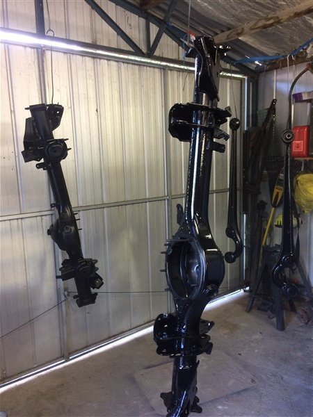
And then my original factory locked LJ78 one, along with the arms got put on a trolley and wheeled out to the the 78.
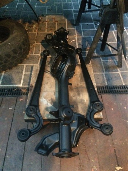
Where I bolted the trailing arms loosely to the axle. (its important to do all the trailing arm/radius arm and panhard rod bolts only finger tight until the vehicle is back on the ground with the wheels on and is given a quick bounce up and down on the suspension, then everything can be torqued up.)
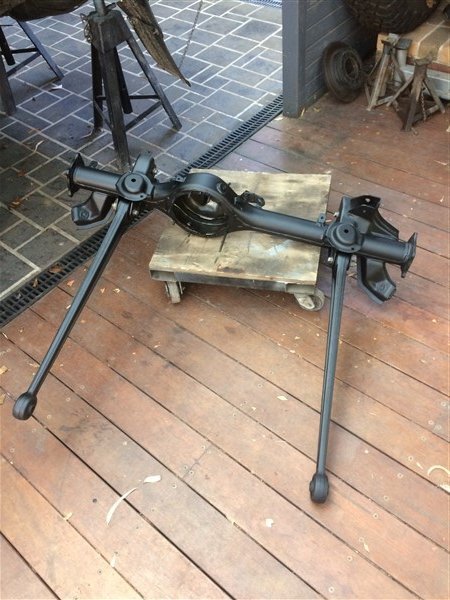
I could then push the whole thing under The 78 and bolt the arms to the chassis.
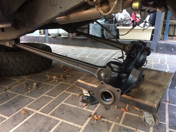
I then swapped the trolley for the trolley jack.
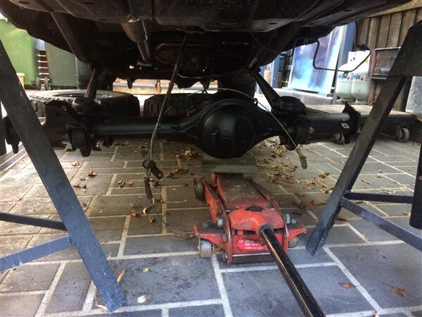
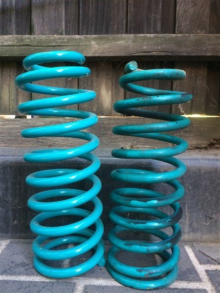
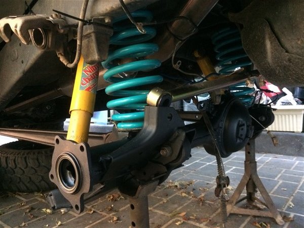
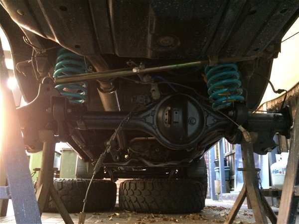
Then it was time to fit the springs.
After our first off road trip in QLD I realised I needed to change the rear springs for the stiffer +150kg ones I had, because the softer ones were bottoming out at times.
Stiffer on the left, old softer ones on the right.
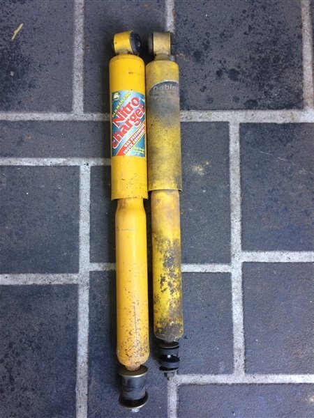
And I also decided to change the rear shocks for the slightly longer OME ones that I had.
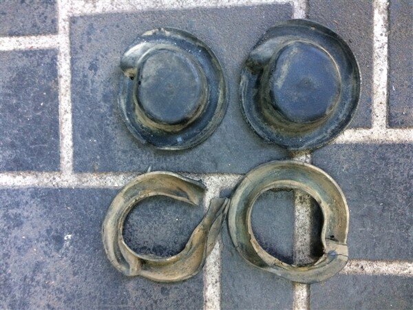
And the final part to change were the bottom spring rubbers as they were badly worn out and looked like the previous owner had butchered them.
That lot were all soon fitted.
The panhard rod needed fitting to the axle next.
Now for some reason Superior Engineering dont make (or at least didnt used to make) a panhard rod for the later rectangular headlight Bundera's/Prado's/LandCruiser II's.
The panhard rods are physically identical on the earlier and later suspension setups, the only difference is the bushes on the ends, or to be more specific the metal tube inserts in the bushes.
So in order to properly fit this earlier style panhard rod to my 78 I found a piece of solid rod at work the right diameter and bored a hole through the middle of it on the lathe, because the old tube insert was far too big for my bolt.
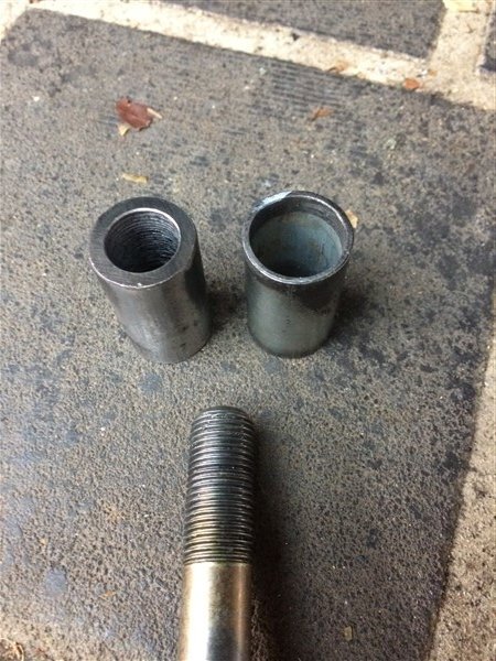
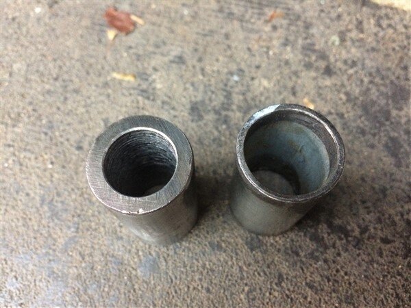
That was soon pushed through the bush using a clamp and the panhard rod was bolted loosely in position.
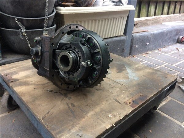
Next I picked up the freshly rebuilt locker!
Now this cost a fortune to have rebuilt, it really did.
But with it being such a rare diff and the fact no one does a ring and pinion that fits it, it needed a highly skilled specialist who was able to make spacers and do all sorts of machining on it. Your average diff/gearbox shop couldnt have done what this guy did.
He also fitted a solid pinion spacer (something that is essential on all Toyota diff rebuilds) and all new bearings.
This is who rebuilt the diff for me:
http://www.ttdrivelines.com.au/
I also got my E locker back from him, which will now be getting fitted in my front diff.
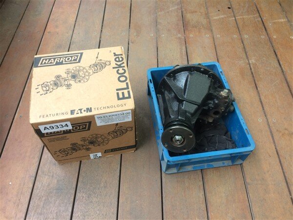
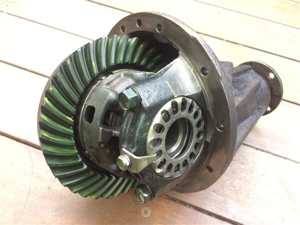
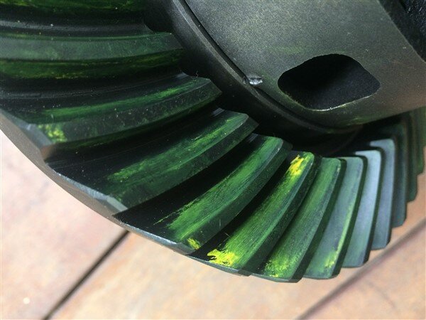
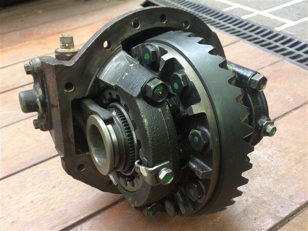
That got put on a trolley and slid under The 78.
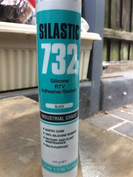
Along with a tube of silastic.
The mating face on the axle casing got a good clean up followed by a good bead of sealant.
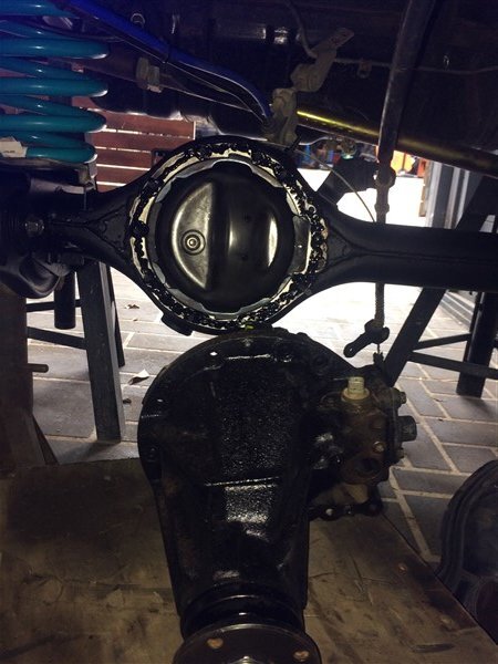
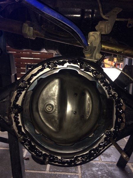
I then lifted the diff into position and then left it sat in place for 30 minutes, before doing all the bolts up. This is to let the sealant set a little bit as otherwise it tends to just all squeeze out when the bolts are done up.
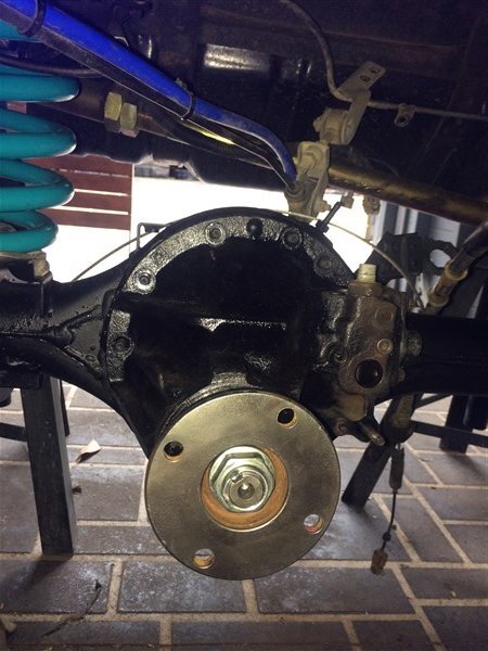
Next the halfshafts and brakes went back on.
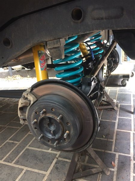
Followed by the wheels/tyres.
I then jacked the rear axle up so the wheels were just off the ground and started the engine and let the clutch out with it in 1st low.
This was because I wanted to see if any power was getting to the actuator plug and I know there is a speed sensor in the gearbox/transferbox that needs to tell the diff lock computer it can engage the locker or not.
But I couldnt get it to send any power to the actuator plug.
I did however find that when manually engaging the locker with a screwdriver through the hole where the actuator bolts on, that the light on the dash does stop flashing and goes to a solid red light when its engaged. So if I do end up converting it to a manual cable operated locker, at least the dash light will still function correctly.
So after testing the actuator some more and deeming it dead, I bolted it on anyway to seal the hole.
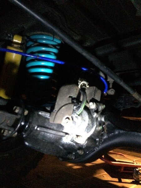
I picked up some oil.
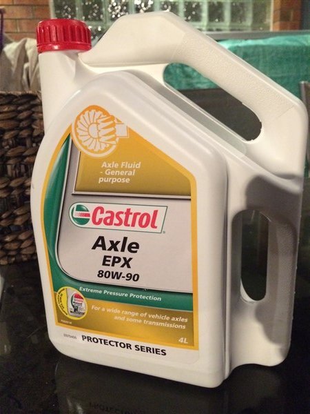
And pumped it in.
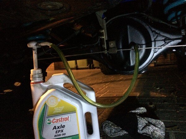
One of the biggest reasons, from what I have read why the locker actuators fail is water getting into them!
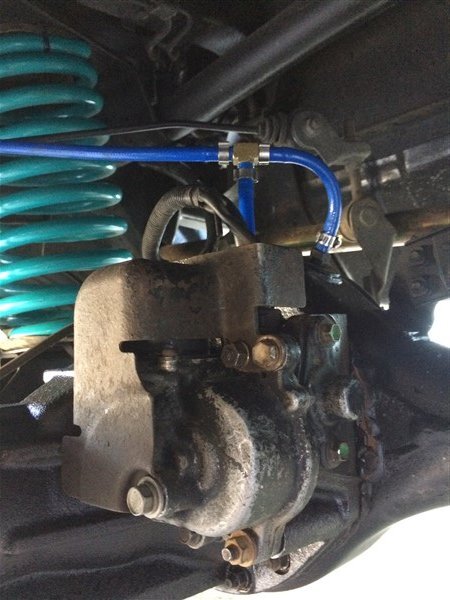
Mine had a breather tube, but it only went as high as the chassis rail.
So my next job was to fit a new breather tube that will run into my diff breathers which run up to the top of my snorkel.
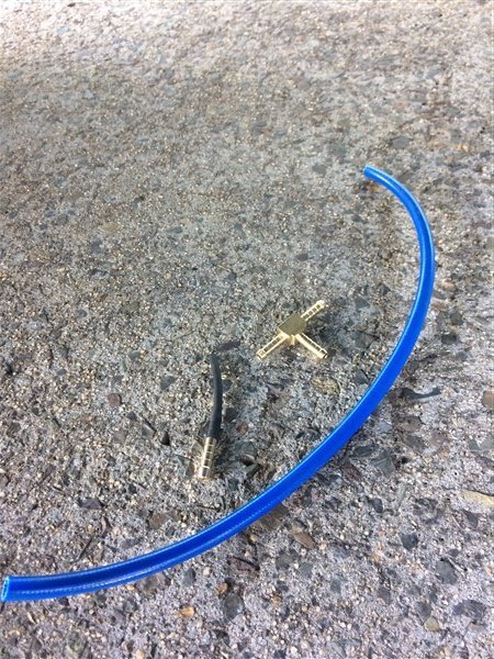
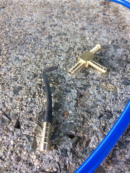
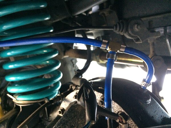
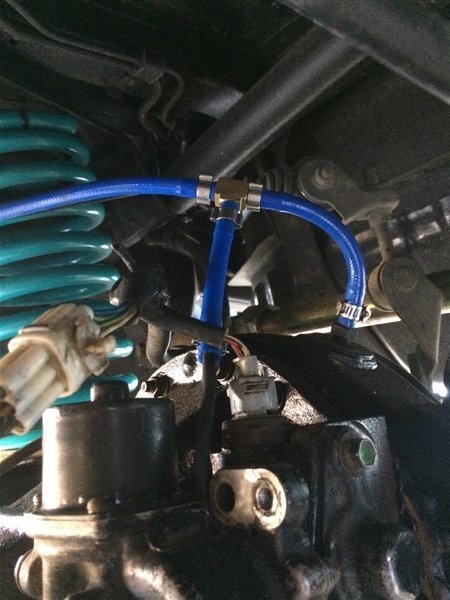
Actuator guard back on and that job was finished.
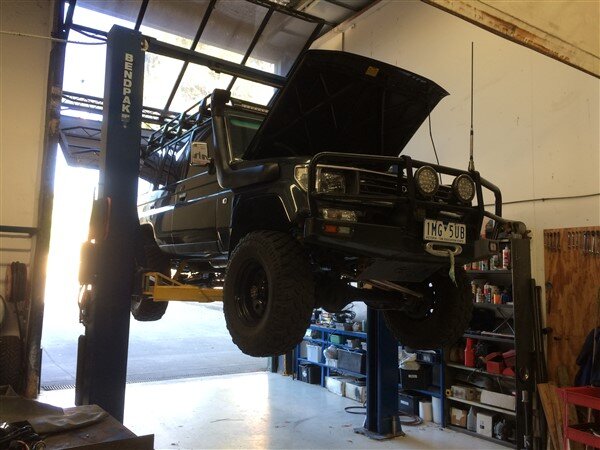
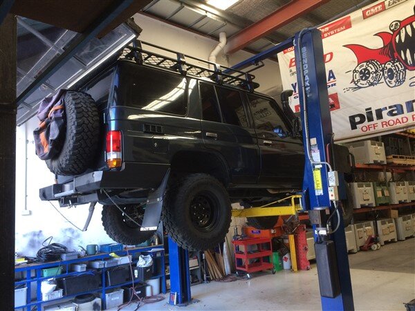
Next I got The 78 on the hoist at work to give it a thorough check over. I checked all the diff/gearbox/Tbox oils, all of which were fine and gave the prop shafts a squirt of grease.
All wheel bearings felt OK and everything looked and felt good.
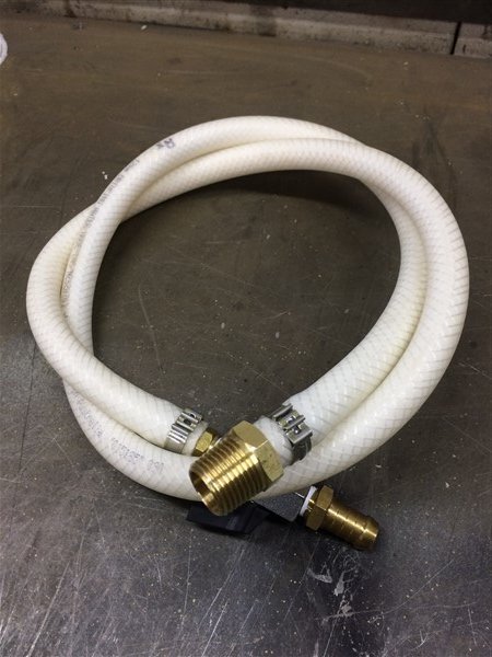
My next job was to plumb in my 50 litre water tank behind my rear seats.
I found most of the parts at work.
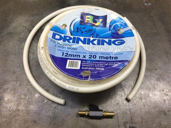
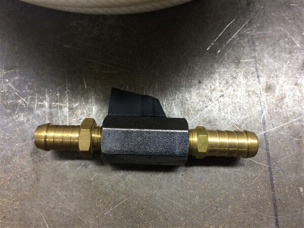
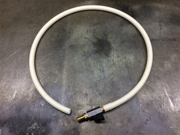
I just had to buy the big fitting that screws into the base of the Boab tank.
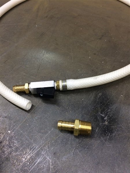
All done and ready to screw on.
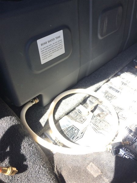
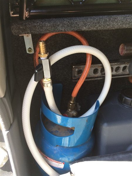
The end of the hose with the tap on will be stored here on top of the gas cylinder and the hose can be pulled out and used with the rear seat in the normal seating position, I will only have to fold the seat before a trip when I'm filling the tank up.
I briefly mentioned this pic in my last update.................
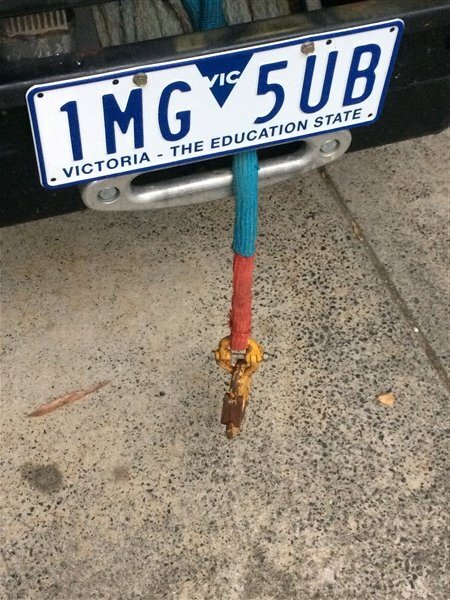
Well I thought I had come up with a brilliant idea!
The car wont fit under the second car port (where I really want to store the vehicle, behind a locked gate), with the roof rack on..................
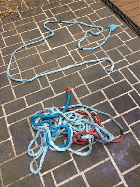
So I pulled the winch rope out, threw it under the car and attached it to the rear recovery point and thought if I winch in it will compress the suspension a few inches and I will be able to drive the car though and then let the tension off the winch rope.
Well it didnt go at all well.
The winch rope snapped and the rope got badly jammed up on the drum.
So after using the foklift truck at work to pull the rope back off the drum, I put it in the Mrs washing machine while she was in bed one morning, then after watching a youtube video detailing how to do it, I made a new loop on the end for the hook to attach to.
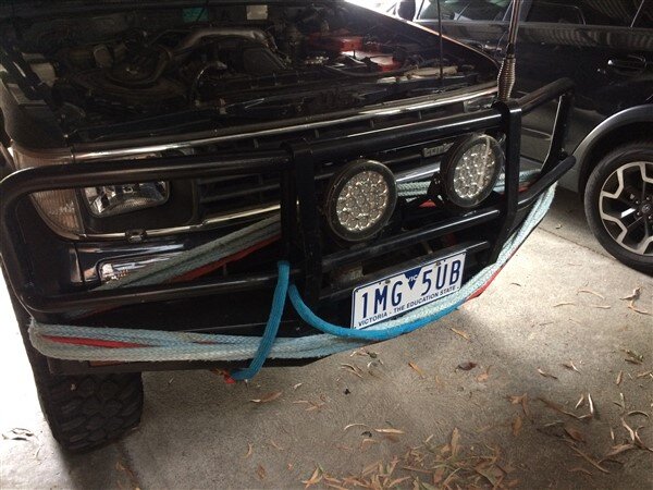
As winch ropes need to be wound on under load I just wrapped it around the bullbar for now.
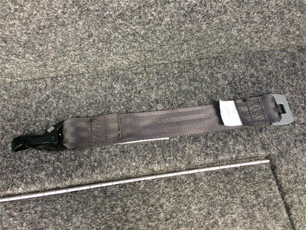
The top tether extension strap arrived.
And the baby capsule was soon strapped into position.
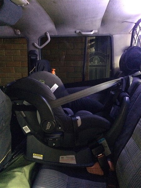
The new top anchor point and extension strap worked perfectly.
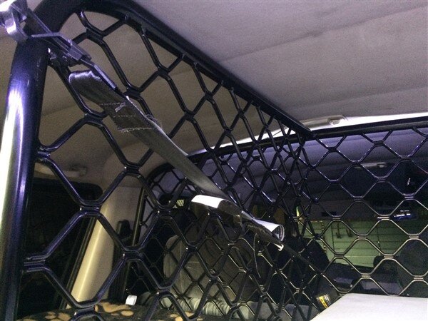
I started loading the car for the Easter trip.
I found that the double stretcher we sleep on, one of the chairs and the compressor fit nicely on the floor under the baby capsule.
But one chair will have to go in the back for now as on this trip I'm hoping the only thing on the roof will be the Oz Tent RV5.
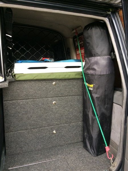
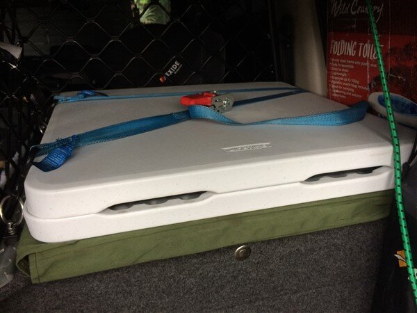
The fold up table and cooking plate fit nicely on top of the drawers and felt very secure once strapped down to the new tie down rails.
So The 78 is now almost ready for next weekends 4 day High Country trip!

The rear axles got a second coat of paint.

And then my original factory locked LJ78 one, along with the arms got put on a trolley and wheeled out to the the 78.

Where I bolted the trailing arms loosely to the axle. (its important to do all the trailing arm/radius arm and panhard rod bolts only finger tight until the vehicle is back on the ground with the wheels on and is given a quick bounce up and down on the suspension, then everything can be torqued up.)

I could then push the whole thing under The 78 and bolt the arms to the chassis.

I then swapped the trolley for the trolley jack.

Then it was time to fit the springs.
After our first off road trip in QLD I realised I needed to change the rear springs for the stiffer +150kg ones I had, because the softer ones were bottoming out at times.
Stiffer on the left, old softer ones on the right.

And I also decided to change the rear shocks for the slightly longer OME ones that I had.

And the final part to change were the bottom spring rubbers as they were badly worn out and looked like the previous owner had butchered them.

That lot were all soon fitted.

The panhard rod needed fitting to the axle next.

Now for some reason Superior Engineering dont make (or at least didnt used to make) a panhard rod for the later rectangular headlight Bundera's/Prado's/LandCruiser II's.
The panhard rods are physically identical on the earlier and later suspension setups, the only difference is the bushes on the ends, or to be more specific the metal tube inserts in the bushes.
So in order to properly fit this earlier style panhard rod to my 78 I found a piece of solid rod at work the right diameter and bored a hole through the middle of it on the lathe, because the old tube insert was far too big for my bolt.


That was soon pushed through the bush using a clamp and the panhard rod was bolted loosely in position.
Next I picked up the freshly rebuilt locker!

Now this cost a fortune to have rebuilt, it really did.

But with it being such a rare diff and the fact no one does a ring and pinion that fits it, it needed a highly skilled specialist who was able to make spacers and do all sorts of machining on it. Your average diff/gearbox shop couldnt have done what this guy did.

He also fitted a solid pinion spacer (something that is essential on all Toyota diff rebuilds) and all new bearings.
This is who rebuilt the diff for me:
http://www.ttdrivelines.com.au/
I also got my E locker back from him, which will now be getting fitted in my front diff.


That got put on a trolley and slid under The 78.

Along with a tube of silastic.

The mating face on the axle casing got a good clean up followed by a good bead of sealant.


I then lifted the diff into position and then left it sat in place for 30 minutes, before doing all the bolts up. This is to let the sealant set a little bit as otherwise it tends to just all squeeze out when the bolts are done up.

Next the halfshafts and brakes went back on.

Followed by the wheels/tyres.
I then jacked the rear axle up so the wheels were just off the ground and started the engine and let the clutch out with it in 1st low.
This was because I wanted to see if any power was getting to the actuator plug and I know there is a speed sensor in the gearbox/transferbox that needs to tell the diff lock computer it can engage the locker or not.
But I couldnt get it to send any power to the actuator plug.
I did however find that when manually engaging the locker with a screwdriver through the hole where the actuator bolts on, that the light on the dash does stop flashing and goes to a solid red light when its engaged. So if I do end up converting it to a manual cable operated locker, at least the dash light will still function correctly.
So after testing the actuator some more and deeming it dead, I bolted it on anyway to seal the hole.

I picked up some oil.

And pumped it in.

One of the biggest reasons, from what I have read why the locker actuators fail is water getting into them!
Mine had a breather tube, but it only went as high as the chassis rail.
So my next job was to fit a new breather tube that will run into my diff breathers which run up to the top of my snorkel.


Actuator guard back on and that job was finished.

Next I got The 78 on the hoist at work to give it a thorough check over. I checked all the diff/gearbox/Tbox oils, all of which were fine and gave the prop shafts a squirt of grease.
All wheel bearings felt OK and everything looked and felt good.


My next job was to plumb in my 50 litre water tank behind my rear seats.
I found most of the parts at work.


I just had to buy the big fitting that screws into the base of the Boab tank.

All done and ready to screw on.


The end of the hose with the tap on will be stored here on top of the gas cylinder and the hose can be pulled out and used with the rear seat in the normal seating position, I will only have to fold the seat before a trip when I'm filling the tank up.

I briefly mentioned this pic in my last update.................

Well I thought I had come up with a brilliant idea!

The car wont fit under the second car port (where I really want to store the vehicle, behind a locked gate), with the roof rack on..................
So I pulled the winch rope out, threw it under the car and attached it to the rear recovery point and thought if I winch in it will compress the suspension a few inches and I will be able to drive the car though and then let the tension off the winch rope.

Well it didnt go at all well.

The winch rope snapped and the rope got badly jammed up on the drum.
So after using the foklift truck at work to pull the rope back off the drum, I put it in the Mrs washing machine while she was in bed one morning, then after watching a youtube video detailing how to do it, I made a new loop on the end for the hook to attach to.


As winch ropes need to be wound on under load I just wrapped it around the bullbar for now.

The top tether extension strap arrived.

And the baby capsule was soon strapped into position.

The new top anchor point and extension strap worked perfectly.


I started loading the car for the Easter trip.
I found that the double stretcher we sleep on, one of the chairs and the compressor fit nicely on the floor under the baby capsule.
But one chair will have to go in the back for now as on this trip I'm hoping the only thing on the roof will be the Oz Tent RV5.

The fold up table and cooking plate fit nicely on top of the drawers and felt very secure once strapped down to the new tie down rails.

So The 78 is now almost ready for next weekends 4 day High Country trip!


- Joined
- Oct 13, 2010
- Messages
- 6,055
- Country Flag
And the final update for today.........................
Yesterday it was time for a little shake down trip at my local State Forrest, Toolangi!
With dog, baby and wife loaded we were off!
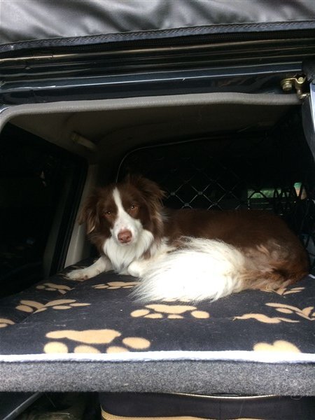
And soon heading in via the infamous Rocky Track.
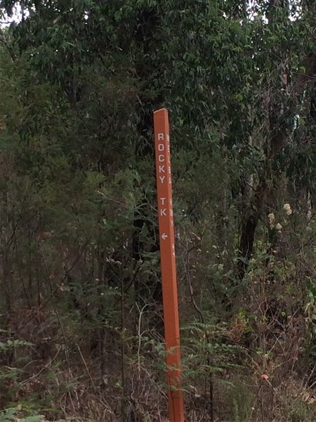
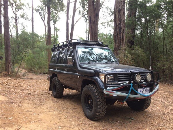
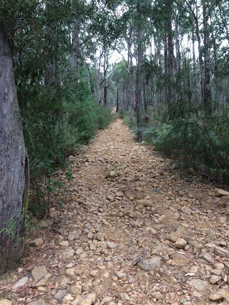
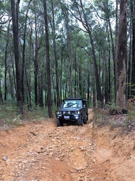
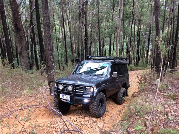
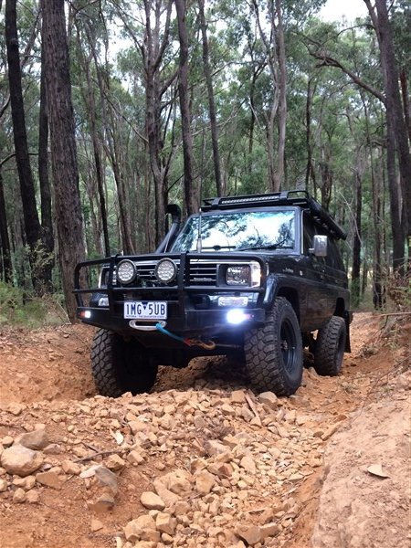
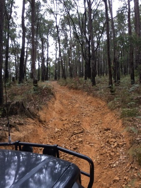
Doesnt look too extreme in the pics but its pretty steep and is all loose rock with some large rock steps half way up!
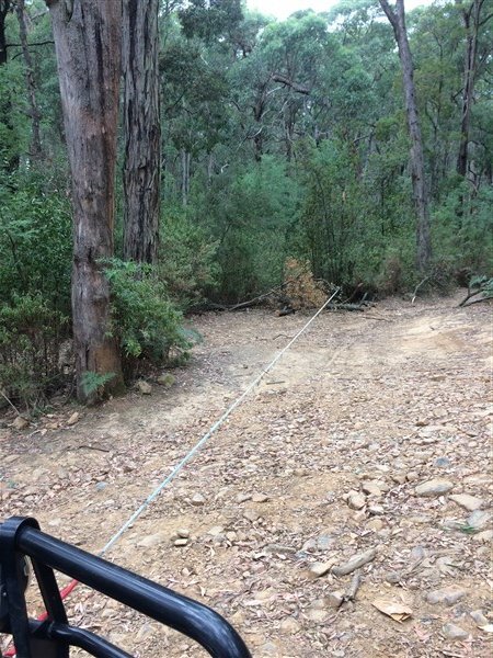
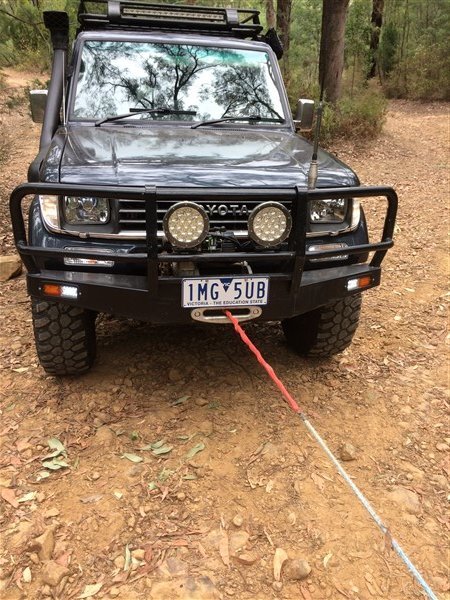
First though I wanted to wind my winch rope in under load encase I would need to use it.
So I hooked it up to a tree and walked in front of the car, guiding the winch rope onto the drum as I winched in.
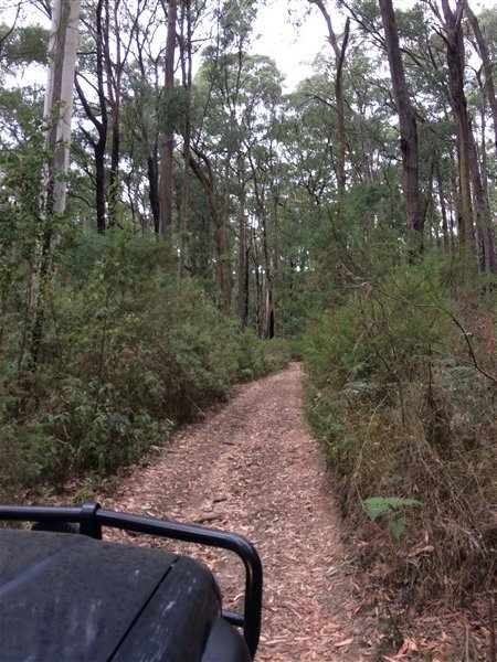
Then we had a little drive along an easy track.
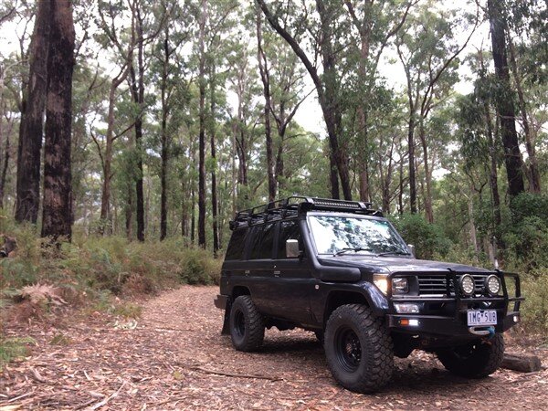
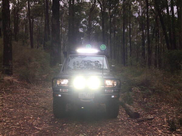
A little light show!
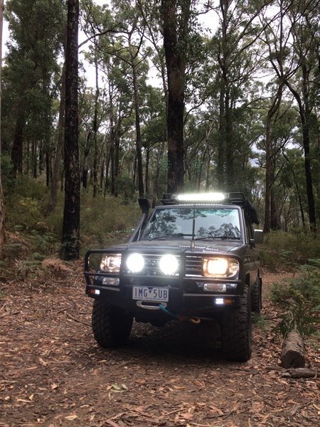
I really need to test it in the dark, especially as I have also fitted a Piranha Super Loom which I forgot tot mention in my electrical updates.
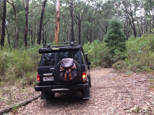
That track soon ended in a dead end sadly so we back tracked to the start of Rocky Track.
I knew there was a chicken track but I had never driven it before but decided to give it a go.
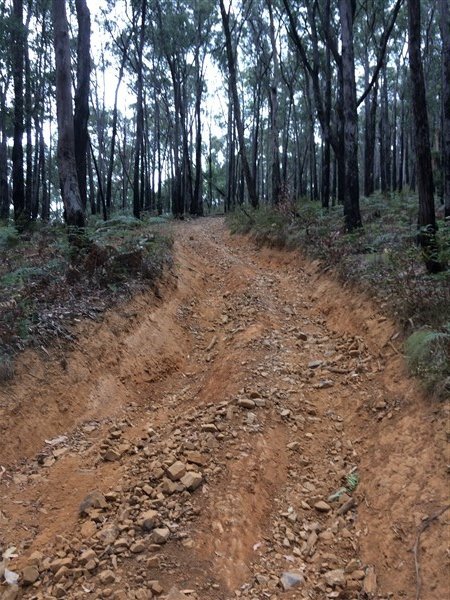
Pics dont do it justice for how steep and rocky it is.
Frustratingly we lost forward motion at this point.
Had I had working lockers I could have driven straight up, but with open diffs I was just spinning wheels!
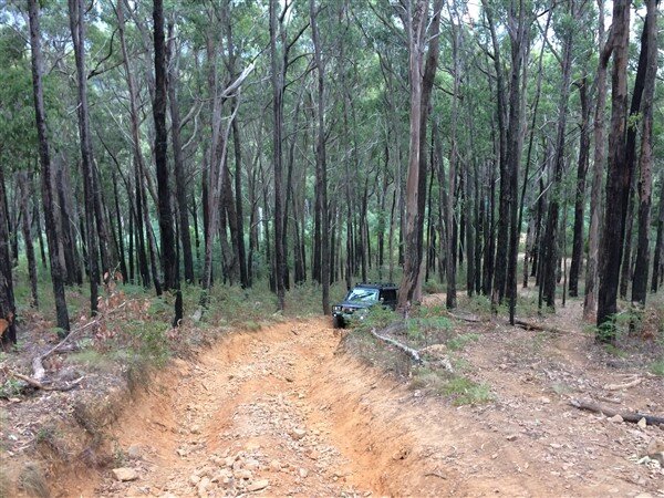
I considered winching but with the family in the car and a storm rolling in I decided to reverse back down.
We stopped at the bottom to let the dog out and to feed and change the boy and I got a few pics before it started raining heavily.
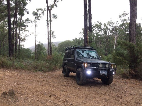
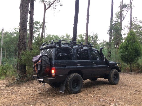
Then we just headed home.
I need to grab a map from work of the forest for next time so I can enter on one of the easier tracks.
I also need to have working diff locks so that I can just put them in at the start of tricky sections and then just safely drive up with minimum wheel spin as its much safer that way and does a lot less damage to the track and puts much less strain on the vehicle!
So The 78 is virtually ready for next weeks trip.
I'm going to start making the rock sliders/side steps this week for it and then they and the rear bumper can be sand blasted, electroplated and powdercoated. Once thats done and the lockers are sorted out this vehicle will be virtually finished and ready to start using more regularly on trips!
Then I can finally crack on with my other one and get that back on the road.
Yesterday it was time for a little shake down trip at my local State Forrest, Toolangi!
With dog, baby and wife loaded we were off!


And soon heading in via the infamous Rocky Track.


Doesnt look too extreme in the pics but its pretty steep and is all loose rock with some large rock steps half way up!

First though I wanted to wind my winch rope in under load encase I would need to use it.
So I hooked it up to a tree and walked in front of the car, guiding the winch rope onto the drum as I winched in.


Then we had a little drive along an easy track.


A little light show!

I really need to test it in the dark, especially as I have also fitted a Piranha Super Loom which I forgot tot mention in my electrical updates.


That track soon ended in a dead end sadly so we back tracked to the start of Rocky Track.
I knew there was a chicken track but I had never driven it before but decided to give it a go.

Pics dont do it justice for how steep and rocky it is.
Frustratingly we lost forward motion at this point.

Had I had working lockers I could have driven straight up, but with open diffs I was just spinning wheels!


I considered winching but with the family in the car and a storm rolling in I decided to reverse back down.

We stopped at the bottom to let the dog out and to feed and change the boy and I got a few pics before it started raining heavily.


Then we just headed home.
I need to grab a map from work of the forest for next time so I can enter on one of the easier tracks.
I also need to have working diff locks so that I can just put them in at the start of tricky sections and then just safely drive up with minimum wheel spin as its much safer that way and does a lot less damage to the track and puts much less strain on the vehicle!

So The 78 is virtually ready for next weeks trip.

I'm going to start making the rock sliders/side steps this week for it and then they and the rear bumper can be sand blasted, electroplated and powdercoated. Once thats done and the lockers are sorted out this vehicle will be virtually finished and ready to start using more regularly on trips!
Then I can finally crack on with my other one and get that back on the road.
- Joined
- Oct 13, 2010
- Messages
- 6,055
- Country Flag
Hi Ben,
Have you thought about converting the locker to air operated? As long as you use a spring return actuator then it will always unlock as soon as you turn it off.
I bought a locker off eBay cheap with no actuator, just need a new R+p (it probably would have been cheaper just to buy a locker for my diff at the end of it)
I have and I'm trying to stay away from having a permanently mounted compressor in the vehicle.

But I'm open to ideas and its not a bad idea.
Do you have any links to the actuators? Or any build threads where people have done it?

- Joined
- May 26, 2014
- Messages
- 4,751
- Country Flag
Great work mate. Very neat work on the wiring, labour intensive ime.
judging by the colour of that cuppa, you can get a decent brew in aus?!
judging by the colour of that cuppa, you can get a decent brew in aus?!
doyle61
Member
- Joined
- Dec 19, 2013
- Messages
- 136
- Country Flag
Great updates as usual Ben. I always had the idea of using an internal in/out switch for when I eventually get myself a winch. I see where your going with the permanently mounted one on the bullbar aswell but think I'll go for the factory control there myself. The plug is a great idea aswell lad. When I took the axles off my lj70 I also noticed the short breather pipes and was thinking of what to do, I think your idea is the way forward.
All good stuff Ben, except snapping the rope.
How old is that rope?
Mine is getting on 10 years and IMO it’s well past its useful life (under max loads that is), I’m always waiting for it to snap on me...
I really would like to hear that you got the leccy actuator to work, or found a replacement at a reasonable price, I’m sure it’s the best option.
You had air lockers before IIRC, and had problems with them, I think.
Great post as usual, keep it up Ben, we love them...
If all else fails Ben, see if you’ve got a motor rewinder nearby or if not you could post to Robson and Francis over here. Long winded I know but would probably be cheaper in the long run. Just a thought.
Last edited:
Ash Awbery
Active Member
- Joined
- Mar 17, 2013
- Messages
- 53
- Country Flag
I’m sure I saved a better thread somewhere but can’t find it.
All I am planning to do is make a new shaft that the fork attaches to then mount a small spring return air ram so one of the pipes is just a breather like the picture. but I already have a on board air system so it’s just a couple of extra pipes.
Great work by the way,
my lj78 is no where near as nice, and I still have the 2LTE so an engine conversion will be on the cards at some point.
rob rule
Member
- Joined
- Feb 23, 2011
- Messages
- 160
hi Ben
inspirational work, as always...
suggestion: silicone grease for sealing the wires/plugs against water
2nd suggestion: tried using handbrake in place of no diff lock - just partially apply to prevent wheel spin on the free wheel (only on rear axle 0f course..) for only as long as you need to get traction...
cheers
- Joined
- Oct 13, 2010
- Messages
- 6,055
- Country Flag
Thanks guys. 
Thanks mate.

I couldnt have emigrated here if they didnt have decent Tea!
I start every day with a litre of Tetley's extra strong in my Cadbury's mug (or bucket as the guys at work call it).
Strong, but still quite milky!


Thankfully Tata make better Tea than they do cars and steel over in India!

Thanks mate.
Not sure how old the rope is, it was on my Warn 8274 when I bought it second hand 4 years ago.
I will probably replace it at some point as we have heaps of the stuff at work, but for now I figured I can afford to loose a few meters off the end as it already had 40 meters on the drum!
I agree, I'd rather stick with a factory rear locker setup if possible.
Thanks mate, I will do the tests after the trip and look into a rewind if it needs it.
What normally causes the need for a rewind?
The only reason I ask is I really cant imagine its ever been used that many times in its life.
Awesome thanks mate.
Gives me an option if I cant get the factory actuator working.
OK.........
Tiny update.
My Czech mate Jiri sent me the route he has planned for us for this weekend.
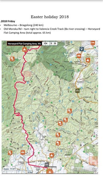
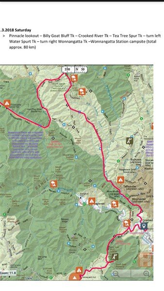
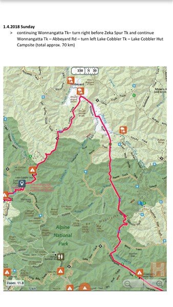
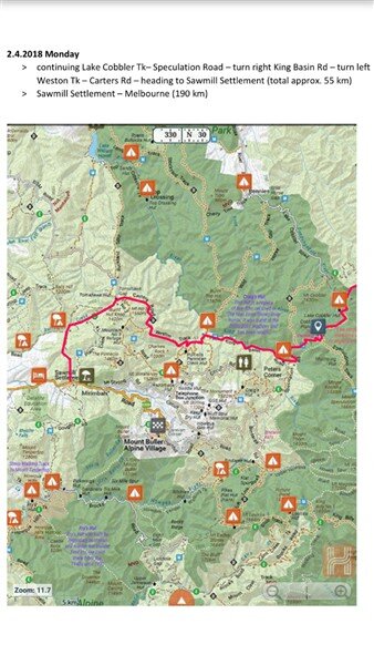
I'm super excited, its years since I've been to the High Country and it was one of my reasons for moving back to Victoria!
I've made a start building the rock sliders!
I thought about trying to get them finished, powder coated and fitted this week before the trip but decided they can wait till next week to be finished and fitted.
I only get 20 mins before work and 20 mins at lunch time to work on these and I'm 2 days in.
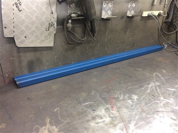
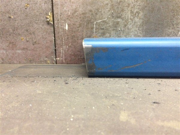
First I cut some 50mm x 50mm x 5mm steel box section to 1700mm long with a slight angle on each end to match the angle on the car, where they will butt up to the mud flaps.
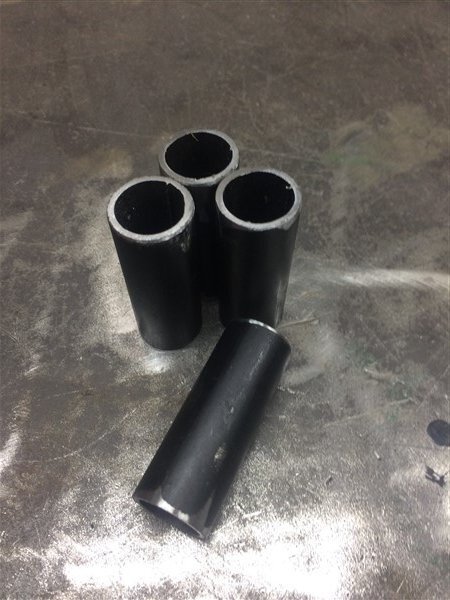
Next I cut some 25mm tube at 70mm long, these bits will get welded in to create my high lift jack adapter sockets.
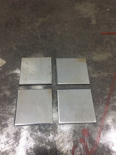
And some 45mm x 45mm x 3mm squares to cap off the ends of the box section.
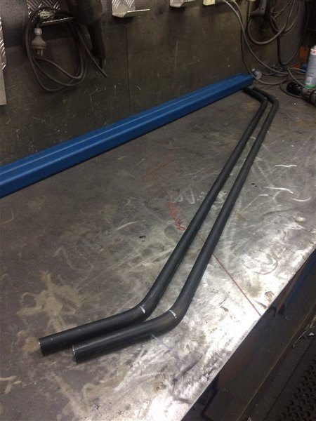
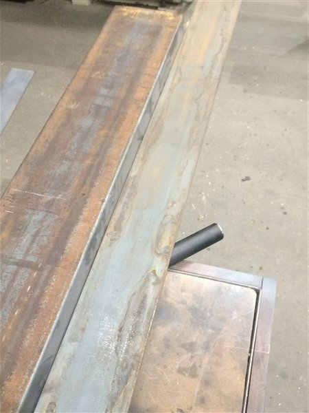
I cut some 25mm tube and put a 45 degree bend on each end.
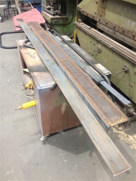
Next I positioned the tube against some heavy channel section and laid a piece of 100mm flat on top of the tube.
Then I could run the angle grinder along the edge of the 100mm flat to cut the tube to length and to the exact angle.
This would mean my tube sections would sit perfectly 100mm out from the body of the rock slider.
Then I positioned the tube on top of a couple of bits of 12mm flat to raise the tube up to the center of the box section, ready for welding.
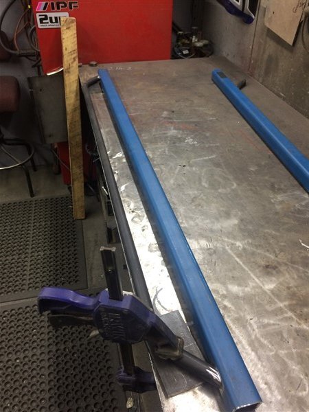
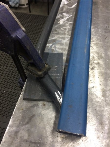
All welded and I also welded the 3mm thick squares on the ends.
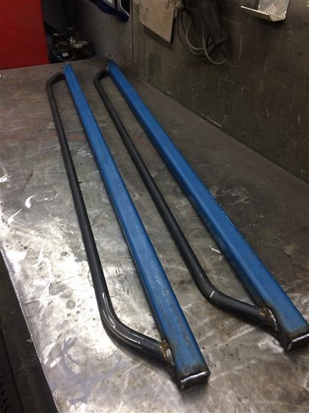
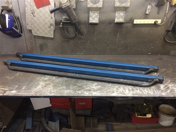
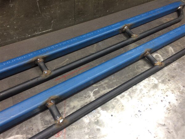
Next I cut some more of the 25mm tube, with 2 x 45 degree cuts on the end to create a notch.
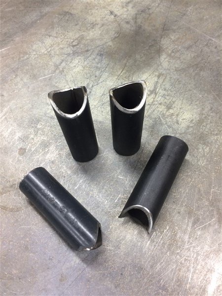
Positioned them between the box section and the tube.
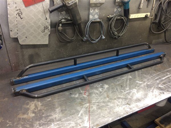
And welded them on.
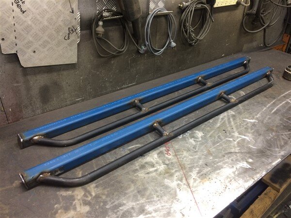
Todays lunch time project was to drill a 27mm hole in each end of each rock slider with a hole saw.
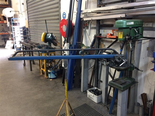
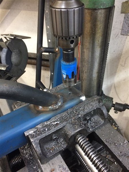
I got those 4 holes drilled and the tube pieces welded in and then I ran out of time. I also forgot to take a pic.
Tomorrows job is to cut some 75mm strips of steel 3mm checker plate and shape the ends to suite the curve of the 25mm tube and weld them on to full enclose those open sections on the top of the rock slider.
That will stop the sides of the car getting covered in crap and also give plenty of grip when standing on them.
Then I just need to build the legs that will clamp around the chassis rails and then they can get powder coated and fitted.
Great work mate. Very neat work on the wiring, labour intensive ime.
judging by the colour of that cuppa, you can get a decent brew in aus?!
Thanks mate.
I couldnt have emigrated here if they didnt have decent Tea!

I start every day with a litre of Tetley's extra strong in my Cadbury's mug (or bucket as the guys at work call it).
Strong, but still quite milky!


Thankfully Tata make better Tea than they do cars and steel over in India!


All good stuff Ben, except snapping the rope.
How old is that rope?
Mine is getting on 10 years and IMO it’s well past its useful life (under max loads that is), I’m always waiting for it to snap on me...
I really would like to hear that you got the leccy actuator to work, or found a replacement at a reasonable price, I’m sure it’s the best option.
You had air lockers before IIRC, and had problems with them, I think.
Great post as usual, keep it up Ben, we love them...
Thanks mate.
Not sure how old the rope is, it was on my Warn 8274 when I bought it second hand 4 years ago.

I will probably replace it at some point as we have heaps of the stuff at work, but for now I figured I can afford to loose a few meters off the end as it already had 40 meters on the drum!
I agree, I'd rather stick with a factory rear locker setup if possible.
If all else fails Ben, see if you’ve got a motor rewinder nearby or if not you could post to Robson and Francis over here. Long winded I know but would probably be cheaper in the long run. Just a thought.
Thanks mate, I will do the tests after the trip and look into a rewind if it needs it.
What normally causes the need for a rewind?
The only reason I ask is I really cant imagine its ever been used that many times in its life.

View attachment 142133 https://forum.ih8mud.com/threads/elocker-to-air-conversion-thread.708474/page-3
I’m sure I saved a better thread somewhere but can’t find it.
All I am planning to do is make a new shaft that the fork attaches to then mount a small spring return air ram so one of the pipes is just a breather like the picture. but I already have a on board air system so it’s just a couple of extra pipes.
Great work by the way,
my lj78 is no where near as nice, and I still have the 2LTE so an engine conversion will be on the cards at some point.
Awesome thanks mate.
Gives me an option if I cant get the factory actuator working.
OK.........
Tiny update.
My Czech mate Jiri sent me the route he has planned for us for this weekend.


I'm super excited, its years since I've been to the High Country and it was one of my reasons for moving back to Victoria!

I've made a start building the rock sliders!
I thought about trying to get them finished, powder coated and fitted this week before the trip but decided they can wait till next week to be finished and fitted.
I only get 20 mins before work and 20 mins at lunch time to work on these and I'm 2 days in.
First I cut some 50mm x 50mm x 5mm steel box section to 1700mm long with a slight angle on each end to match the angle on the car, where they will butt up to the mud flaps.


Next I cut some 25mm tube at 70mm long, these bits will get welded in to create my high lift jack adapter sockets.

And some 45mm x 45mm x 3mm squares to cap off the ends of the box section.

I cut some 25mm tube and put a 45 degree bend on each end.

Next I positioned the tube against some heavy channel section and laid a piece of 100mm flat on top of the tube.
Then I could run the angle grinder along the edge of the 100mm flat to cut the tube to length and to the exact angle.
This would mean my tube sections would sit perfectly 100mm out from the body of the rock slider.


Then I positioned the tube on top of a couple of bits of 12mm flat to raise the tube up to the center of the box section, ready for welding.


All welded and I also welded the 3mm thick squares on the ends.


Next I cut some more of the 25mm tube, with 2 x 45 degree cuts on the end to create a notch.

Positioned them between the box section and the tube.

And welded them on.


Todays lunch time project was to drill a 27mm hole in each end of each rock slider with a hole saw.


I got those 4 holes drilled and the tube pieces welded in and then I ran out of time. I also forgot to take a pic.

Tomorrows job is to cut some 75mm strips of steel 3mm checker plate and shape the ends to suite the curve of the 25mm tube and weld them on to full enclose those open sections on the top of the rock slider.
That will stop the sides of the car getting covered in crap and also give plenty of grip when standing on them.
Then I just need to build the legs that will clamp around the chassis rails and then they can get powder coated and fitted.
Last edited:
Similar threads
- Replies
- 1
- Views
- 386


