Don't like the adverts?  Click here to remove them

Positions of inputs & load outputs along auto 12v wiring

Aurelian

New Member
Joined
Aug 23, 2024
Messages
12
Country Flag
australia
Hey all,

I currently have an auxiliary battery running my fridge. I plan to add solar to the auxiliary now to charge this battery while not driving, and in future I will likely want to add an inverter.

I have a decent-ish understanding of automotive electrical and know how each individual thing works, but when combining them all into a larger system I have a few gaps when it comes to the wiring position of things.

When you look at a typical wiring diagram it's all very neat, with all power sources going directly into the battery, and all load being taken directly from the battery.

This doesn't always fit with reality though, of course.

My question is, what happens if the order of these things along the line is changed. What if the solar input connects inline between the inverter and battery, rather than directly to the battery.

What if devices like a fridge or inverter sit between the battery and solar panels.

Like so.

automotive-wiring.gif


The one thing I'm not sure about is the solar pushing power into the system at different points along the line, before or after load devices pulling power out of it.

In diagram B specifically, the direction of energy flowing "looks" like power from the solar regulator is being driven into the Inverter before the battery, rather than the inverter only pulling from the battery itself.

Does this matter? Or is the whole system effectively the same 'pool' that is just being filled and emptied, regardless of where in the line things sit? And it doesn't matter in what particular things sit as long as they're all ultimately connected to positive and negative (with appropriate gauge wire, fuses, etc. obviously).

Could you, for example, have a single paired-cable coming from the battery with a 3-way split at the end with 3 Anderson plugs, and have your fridge, inverter, and solar all connected at the same end , drawing and feeding power through the single cable to the battery simultaneously. Like this...

Untitled-2.jpg


Thanks all.
 
Last edited:
Pretty sure it dosnt make a difference, i know all my earths go to a busbar and then connect to the battery terminal, in effect youre just moving the battery terminal, like in your last diagram above butr i do still have the positives on the terminal, also have a redarc which is where the solar would connect to which makes it slightly different (but the same?). when everyone else wakes up im sure they'll have more definite answers. @StarCruiser is rather good at all this sort of thing.
 
Electrically, all the above diagrams amount to the same thing as everything is connected in parallel. I'm assuming your solar would have some form of output/charge controller.
 
I'm assuming your solar would have some form of output/charge controller.

Yep. Obviously my diagrams are over-simplified.

More specifically I have a BCDC controller, battery, various loads, solar MPPT, etc. All the usual stuff, I'm across all that.

In my previous 4WD though (Prado 150) everything was connected directly to/from the aux battery. I've recently bought a new LC76 series so having to do the whole 12v install again fresh on the different platform which requires a different approach.

I will have a lithium deep cycle in the boot. Still mulling over options, but I was thinking/hoping it all worked the same regardless of the connection order (parallel, as you say) as that would let me run 1 cable from the boot to the tow bar with 3 Anderson plugs to connect everything there.

Obviously that single cable is a lot simpler/cleaner to get through the floorpan etc. than having to run individual cables for each different "in" and "out" line.
 
Last edited:
Best to take the solar to your charge controller MPPT and then to the battery directly via a suitable fuse and ideally a disconnect. Take the outputs via a suitably heavy fuse and disconnect to your inverter. Then another disconnect and fuse for your loads to a fuse panel where each load is fused to the size of the cable. Each disconnect can be commoned with a short thick cable to the battery positive but make certain this cannot be damaged (in an accident). Ideally you should have the fuses first at the battery then through a disconnect and out to loads. It’s so important with Lithium batteries to do this AND make absolutely certain nothing can bridge the battery terminals. Yes it’s 12v but the current delivered is potentially very high for short periods. It’s also essential to use some form of voltage cut off to prevent over charging and over discharging which is very easy to do when unattended.
 
Ideally you should have the fuses first at the battery then through a disconnect and out to loads. It’s so important with Lithium batteries...

Hey @StarCruiser

For clarity, why do you stress a fuse and a disconnect, as opposed to a circuit breaker which serves both purposes?

Or why not just fuse it, without the disconnect?

( Or perhaps I'm reading your message too literally? )

I understand the point of fuses/breakers as protection against shorts, and how voltage is irrelevant as it's the massive amperage dump in a shortcircuit that does the damage, but it seems like a lot of 'double handling' protection in what you've outlined above.

Personally, I've always used midi fuses, and never a breaker, but was looking into them as potentially part of this. What the case for using both on each connection?
 
Last edited:
Don't like the adverts?  Click here to remove them
A disconnect can be a switch, removable fuse, circuit breaker or a relay and you can use as many or as few as you like as long as the cable has protection for its size. A circuit breaker is going to be suitable as long as it is a DC breaker that is thermal and magnetic suitable to break high short circuit currents. The inverter will take a heavy current and a fuse may be the best way to protect the cables that feed this unless the cables used will carry the current until the battery is depleted without damage under short circuit which is where the protection needs to be as close to the battery as possible. There are reasonable battery post mount fuseboxes that have starter fusing provision with several hundred amp fuses that may be a compact way to fuse several circuits of different sizes if suitable. A single disconnect on the battery would be the minimum if suitably large but there needs to be relays to disconnect charge and discharge to protect the battery from damage linked to the BMS.
 
Also worth noting that there are a number of products on the market that you can use to connect and control your battery inputs and outputs. Victron do a large range of such products but there are many others.

They will have inputs for solar/ alternator and outputs for your inverter/ 12v appliances. They also have lots of electrical trickery so you can monitor solar input/ battery load/ remaining battery time under certain loads etc etc usually linked to a phone app. They are quite expensive, but in my opinion they will add value and make the wiring much simpler.
 
Hey @nick_the_fish ,

Yep, I'm aware. I actually have a few of the Victron MPPT controllers and Smart Battery Sensors etc. as part of various setups.

I don't need the added complexity of a shunt to monitor usage/remaining, etc. as my battery and solar capacity exceeds my needs on a typical daily basis (as cool as it is to have that info).

In hindsight, I probably should have provided more detail on my prospective setup. My specific query here was regarding having multiple input/outputs on the same parallel circuit for wiring simplicity, but due to me being vague on some of the other details we've wandered off-topic a bit here and there.

In any case, I think I have my info for now. Appreciate everyone's input.

I might post back with a more specific wiring diagram if still ponding anything in due course.
 
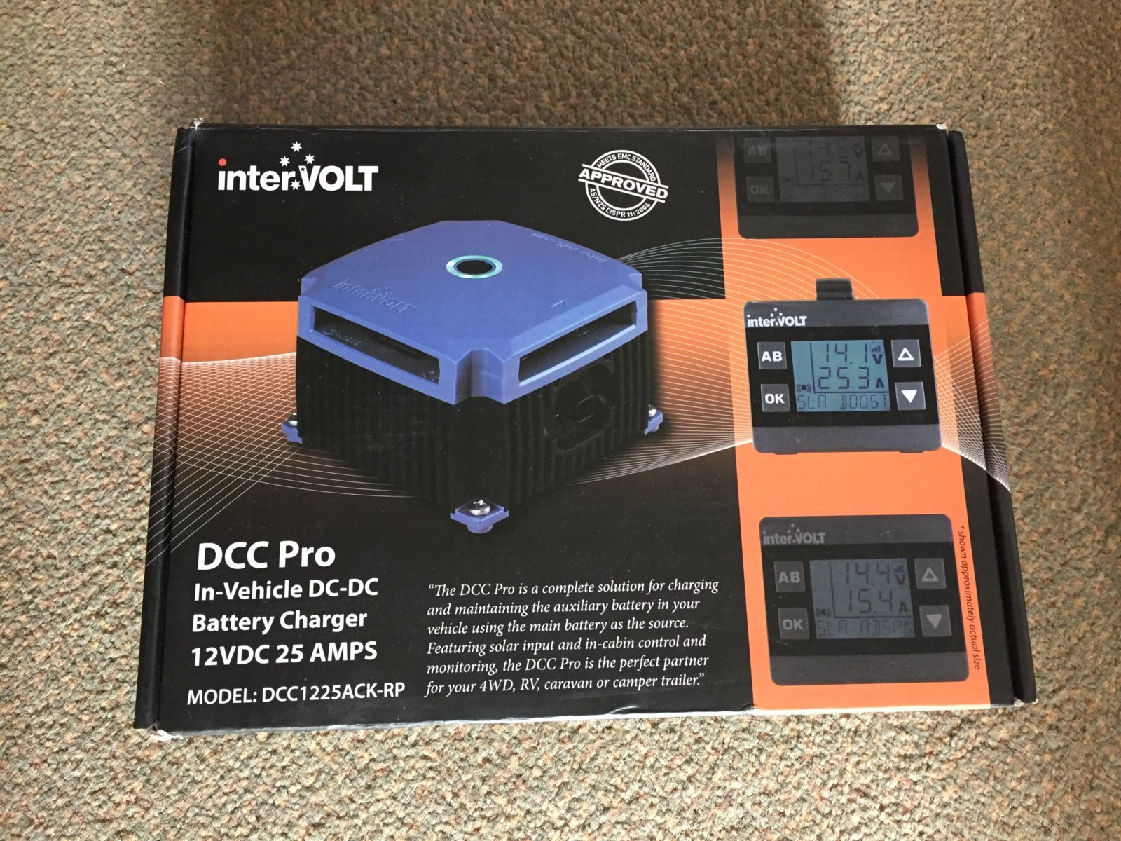
Sounds like you’ve got things sorted for your MPPT etc but if you are in the market for a battery to battery charger that takes solar and can charge a LiFePo4 battery if it has its own BMS then take a look at the Intervolt DCC Pro R2. I have stock of these. There’s a thread on here somewhere about them. Mine is still going strong under the bonnet.
 
...if you are in the market for a battery to battery charger that takes solar...

I've been debating that, actually.

My old setup was about 10 years old, just the usual.... Redarc BCDC charger (non-solar), starter battery, and auxillery 50AH AGM all under the bonnet. Power running to the boot for the fridge etc.

I later added solar with a Victron MPPT connected to the aux, and just connected solar blankets to it when setup at camp.

I now have a 100AH LiFePO4 which will live in the boot. For this build, considering:

Option A) Typical setup with something like the Redarc Alpha25 to change both batteries while driving, and with solar.

That said, my usual activity is drive to camp, setup for 2-3 days with solar out the whole time. I'm, never really in the situation of doing hours of driving without the opportunity to put up solar, while simultaneously drawing tonnes of power from the aux.

With both my fridges running, it's average of about 2AH draw, and I typically do 2-4 hours to get to camp, where I could then plug in the solar.

Once setup, I use about 25AH a night, and have 500W of solar which is more than enough to fully charge that again on even a modestly sunny day.

Option B) I'm considering just adding my MPPT to the lithium battery in the boot, and just run an Anderson plug to the towbar. Means not having to buy a DCDC charger again, and makes the installation 10x simpler.

The "downside" is just between trips, the LiFePO4 battery wouldn't get charged to 100% on the drive home.

Need to get a few trips under by belt with the above, and see if it pans out, I suppose.

If it isn't working as well as I'd hoped, then can add the DCDC charger to fill it the aux while driving as well.

New builds, eh. What to do, what to do.
 
Can you plug your solar in once you get home? Or even have some permanent panels that you plug in while the cruiser is parked up to keep everything topped up? That would save on the DCDC and give free maintenance charging.
 
Looks you you have everything covered, but to comment on your drawings in the first post: (mainly in case someone with less experience reads this thread later).
Whether the difference between the 4 options matter, depends on the cables sizes, plugs, switches and fuses used; as it takes very little resistance to give a voltage drop that matters for a charge controller, a fridge or an inverter. The first diagram (Typical) is the best for that consideration, but there are ways to compensate for losses. Thick cables and good connectors can make the 4 nearly equally good.
Most fridges and inverters have a voltage cut-out which will stop drawing power before the battery is half empty if the resistance in the andersen or in the cable is too high. A charging device need to know the exact voltage at the battery, not the voltage down the line where an inverter has lowered the voltage by several millivolts. Etc.
 
Can you plug your solar in once you get home? Or even have some permanent panels that you plug in while the cruiser is parked up to keep everything topped up? That would save on the DCDC and give free maintenance charging.

Unforuntunately, no.

I'm in undercover parking, with no possibility of changing that.

So it's go all in with a BCDC charger as well, or solar when camped only and partial discharge on the way home.
 
Whether the difference between the 4 options matter, depends on the cables sizes, plugs, switches and fuses used; as it takes very little resistance to give a voltage drop that matters for a charge controller, a fridge or an inverter. The first diagram (Typical) is the best for that consideration, but there are ways to compensate for losses. Thick cables and good connectors can make the 4 nearly equally good.

Yep, so none of that would be an issue for me.

In my last setup, from the aux battery to the load distribution block was 6AWG.

All my load distribution outputs were all 8AWG to their Anderson plugs. Midi fuses throughout, not blade fuses.

Then the fridges, inverter, etc. plugged in from there, all with minimal length cables.

More than healthy gauge wiring throughout. I would run the same in the new setup.
 
As a general rule, unless the battery will deplete before the cable catches fire if short circuited then all smaller cables need appropriate size fuses at the point the size drops to the smaller cable. Seems like that’s what you’re doing. What you’ve suggested in your initial post looks like a ‘bus system’ with tap offs at certain points along a backbone of larger cabling. This is fine for distribution to loads but I suspect would upset the charging if the MPPT were connected along the bus away from the battery. Unless it has a separate volt sensing wire direct to the battery in which case it should work perfectly well. I’m not aware the Victron MPPTs have a voltage sense option like their inverter/chargers do.
 
  • Like
Reactions: uHu
Sounds like you’ve got things sorted for your MPPT etc but if you are in the market for a battery to battery charger that takes solar and can charge a LiFePo4 battery if it has its own BMS then take a look at the Intervolt DCC Pro R2. I have stock of these. There’s a thread on here somewhere about them. Mine is still going strong under the bonnet.
under the bonnet with real world usage ... sounds good
 
...all smaller cables need appropriate size fuses at the point the size drops to the smaller cable. Seems like that’s what you’re doing. What you’ve suggested in your initial post looks like a ‘bus system’ with tap offs at certain points along a backbone of larger cabling.

Yep. I get the finer points, completely understand fusing, etc., the top level 'bus system' was where I wasn't sure.

This is fine for distribution to loads but I suspect would upset the charging if the MPPT were connected along the bus away from the battery. Unless it has a separate volt sensing wire direct to the battery in which case it should work perfectly well. I’m not aware the Victron MPPTs have a voltage sense option like their inverter/chargers do.

Victron's MPPTs don't come with one built-in; they do, however, make a separate Bluetooth temperature/voltage sensor that you can pair with your MPPT controller.
 
under the bonnet with real world usage ... sounds good
They’re neat pieces of kit, super well made in Aus for under bonnet use in Australian heat to deliver 25A all day long.
Here’s my original thread on them.
 
Last edited:
Yep. I get the finer points, completely understand fusing, etc., the top level 'bus system' was where I wasn't sure.


Victron's MPPTs don't come with one built-in; they do, however, make a separate Bluetooth temperature/voltage sensor that you can pair with your MPPT controller.
Ah, yes, I’d forgotten about the Bluetooth temperature and voltage sensor. That should work to keep the charging at the correct voltage. Can’t see why if cables are sized correctly that your bus system shouldn’t work just fine. I have found with a system in my camper that turning off the battery disconnect and leaving the MPPT connected to loads, that the loads continue to function without issue (with loading below the MPPT output limit), probably til the sun goes down.
 
YYY
Back
Top